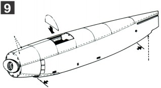
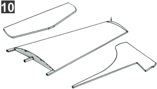
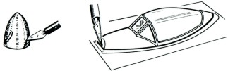
Cut the plastic nose cowl and spinner free from formed sheet (FIG. 9). Carefully cut slots in sides of spinner then cement lightly to propeller. Carefully cut the transparent canopy free from formed sheet (FIG. 10). Scissors may be used if desired. Cement the cowl to the nose of fuselage. Cement canopy to fuselage.
Lightly sandpaper the wing, stabilizer and rudder frames. Cover both sides of stabilizer and rudder with single pieces of tissue - also bottom of wing frames with single sections of tissue. Cover the top of wing frame is covered in two sections as shown above.
Sandpaper fuselage frame lightly to remove all balsa fuzz. Cut out and cement the stiff paper cockpit pattern in place. Cover fuselage with sections of tissue - the side frames first and then the top and bottom areas. Apply the tissue dope only to the edge of balsa frame members that come in contact with the edges of tissue. Cut out paper cowl louvers and cement in place.
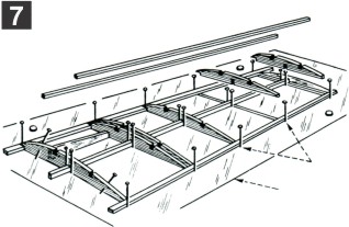
The rudder and stabilizer frames are built over the layouts on opposite side of plan. Pin wax paper over layouts and then pin the die-cut balsa pieces in position. Cut and fit the balsa spars and then cut and add rib members (all 1/16" sq. strip stock). When dry, remove from wax paper and trim ends of spars as required.
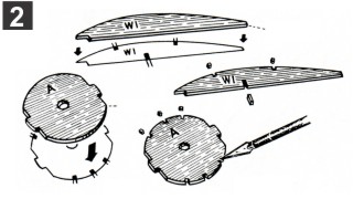
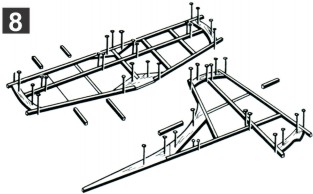
Build the right and left wing panels over layout on other side of plan. Lay plan on work board and pin sheet of wax paper over layouts. Start by pinning the bottom spar in place and then cementing W-6 to spar. Cement ribs to bottom spar and then add the leading and trailing edges. Finally, cement the DIE-CUT wing tip W-7 and top spar in place.
KIT 904
Douglas A1H Skyraider
17¼" Wing Span - 14¼" Overall Length - Approx Scale: ½"=1'-0"
COPYRIGHT 1970 BY PAUL K. GUILLOW, INC.
Set fuselage formers over the patterns shown and mark stringer notches with pencil (FIG. 1). Next cut out the notches with point of a razor blade or knife, (FIG. 2). Next, cement 1/16" x 1/8" braces to former A. Mark and notch all wing ribs in same manner.
When assembling model, check with three view plan to see that parts are in correct alignment. Do this before cement holding parts together hardens. Assemble the model as follows: Cement the stabilizer in slot at fuselage tail. Cement the rudder to top of tail of fuselage. Cement wing panels to sides of fuselage - be sure to score tissue where root ribs join fuselage to insure a strong joint. Check for
|
|
proper wing dihedral before cement hardens - see front view.
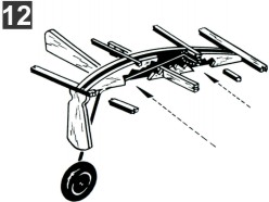
Add paper engine cowl. Spray model lightly with water to shrink tissue—use an insect sprayer or similar devise. Bend landing gear wires to shape. Cut small hole in tissue and cement landing gear wires to wing ribs. Attach wheels to struts (L1).
Tie one end of rubber motor with about 10" of
|
|
light string. Insert other end into fuselage with nose up so rubber will go through the fuselage and rubber loop. Pull front end of loop through with string. Remove string and slip motor over the propeller hook. Longer flights can be had if you lubricate the rubber with straight castor oil. Purchase about 36" of 1/32" x 3/32" Rubber at your hobby store, lubricate, stretch, wind and you can more than double the original turns.
|
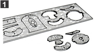
Press all die-cut parts from balsa sheets, work carefully to avoid splitting. Use point of single edge razor blade to free any piece that fails to punch out easily. If you split one of the die-cut pieces, cement together and let dry. Arrange the parts on a board or table with the printed side up for quick identification.
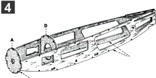
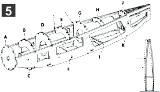
Set former "D" in position between side frames but DO NOT cement at this time. Next cement former "A" between the nose ends of frames - hold with fingers or rubber band until dry. Do not squeeze too hard or you will be apt to crush the frame and consequently have to repair it.
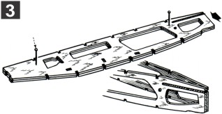
Clear the former notches in fuselage side frames with point of blade. Pin the two side frames together on a work board (FIG.3). Apply a generous coat of cement to the tail end of frames (ARROW). After cement dries hard, remove pins and open nose end of frames (FIG. 4). The cement will act as a hinge while holding tail end together.
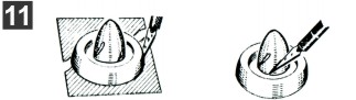
Apply a generous coat of cement to disk Unit AA and place it on former A. (FIG. 6). Note: DO NOT get cement in recessed area where wood bearing is located. Cement (GENEROUSLY) 1/16" sq. braces to back of formers J and K (FIG. 7). Use 1/16" x 1/8" stock to make parts for FIG. 8 then cement in place, — see notching patterns. Cement tail wheel gear in place.
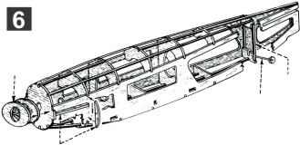
Line up side frames carefully (FIG. 5) and then set the rest of formers into place. After checking the alignment, cement all corners where formers and frames join. (FIG. 5A) Cut and cement 1/16" sq. stringers in place as shown in large perspective at right. Stringers are cut from sheet of balsa strip stock.
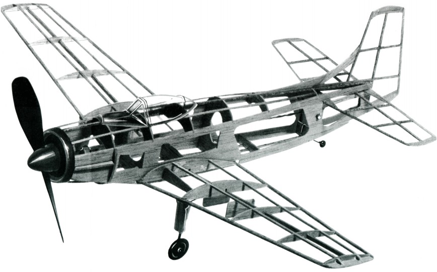
PHOTOGRAPH OF FRAMES
Note: frames should be tissue covered before assembly.
Building the Douglas A1H Skyraider
CEMENT FORMER A TO FUSELAGE WITH STRIPS ON THE BACKSIDE.
THIS BOTTOM SECTION IS LEFT OPEN
COVER BOTTOM SECTION BETWEEN ARROWS WITH SINGLE SECTION OF TISSUE
WING TIP SECTION COVERED SEPARATELY
LIGHTLY CEMENT SPINNER TO PROPELLER
Make 1 right and 1 left landing gear - see patterns. To install in tissue covered wing— cut away tissue between the two W-2 ribs, insert wire into indicated area. Slit tissue and generously cement at indicated area only.
GENEROUSLY CEMENT WIRE BETWEEN RIBS - HERE ONLY