KIT 901
No. American T-28D Trojan
16" Wing Span - 13" Overall Length - Approx Scale: 13/32"=1'-0"
COPYRIGHT 1967 BY PAUL K. GUILLOW, INC.
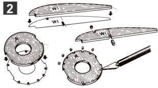
Set fuselage formers over the notching patterns shown below and mark stringer notches with pencil (FIG. 1). Next cut out the notches with point of a razor blade or knife, (FIG. 2). Cement 1/16" sq. cross braces to formers D1, F1 and G. Mark notch ribs in same manner as formers.
When assembling model, check with three view plan to see that parts are in correct alignment. Do this before cement holding parts together hardens. Assemble the model as follows: Cement the stabilizer to the top of fuselage tail. Cement the rudder to top of stabilizer and tail of fuselage. Cement wing panels to sides of fuselage - be sure to score tissue where root ribs join fuselage to insure a strong joint.
|
|
Check for proper wing dihedral before cement hardens - see front view. Add wing fillets (W8). Spray model lightly with water to shrink tissue - use an insect sprayer or similar device. Bend landing gear wires to shape. Cut small hole in tissue and cement nose gear solidly to (A1) and former (B). Attach struts (L1) and (L2). Cement main gear wires to bottom of wing ribs and strut (L1). Attach wheels.
|
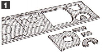
Press all die-cut parts from balsa sheets, work carefully to avoid splitting. Use point of single edge razor blade to free any piece that fails to punch out easily. If you split one of the die-cut pieces, cement together and let dry. Arrange the parts on a board or table with the printed side up for quick identification.
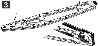
Set former "C" in position between side frames but DO NOT cement at this time. Next cement former "A" between the nose ends of frames - hold with fingers or an elastic band until dry. Do not squeeze too hard or you will be apt to crush the frame and consequently have to repair it.
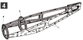
Clear the former notches in fuselage side frames with point of blade. Pin the two side frames together on a work board (FIG.3). Apply a generous coat of cement to the tail end of frames (ARROW). After cement dries hard, remove pins and open nose end of frames (FIG. 4). The cement will act as a hinge while holding tail end together.
Build the right and left wing panels over layout on other side of plan. Lay plan on work board and pin sheet of wax paper over layouts. Start by pinning the bottom spar in place and then cementing W-6 to spar. Cement ribs to bottom spar and then add the leading and trailing edges. Finally cement tip W-7 and the top spar in place
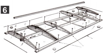
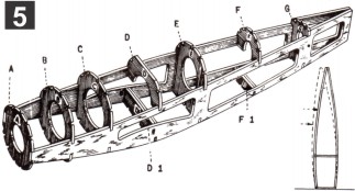
Line up side frames carefully (FIG. 5) and then set the rest of the formers in place. After checking the alignment, cement all corners where formers and frames join (FIG. 6). Cut and cement the 1/16" sq. stringers in position as shown in large perspective at right. Stringers are cut from sheet of balsa strip stock. Add "A1" - see side view.
Sandpaper fuselage frame lightly to remove all balsa fuzz. Cut out and cement the stiff paper cockpit pattern in place. Cover fuselage frame with sections of tissue - the side frames first and then cover the top and bottom sections. Apply the tissue dope only to the edge of balsa frame members that come in contact with the edges of tissue.
The rudder and stabilizer frames are built over the layouts on opposite side of plan. Pin wax paper over layouts and then pin the die-cut balsa pieces in position. Cut and fit the balsa spars and then cut and add rib members (all 1/16" sq. strip stock). When dry, remove from wax paper and trim the spars to proper length.
THIS BOTTOM SECTION IS LEFT OPEN
ADD "H" AFTER COVERING FRAME
COVER BOTTOM SECTION BETWEEN ARROWS WITH SINGLE SECTION OF TISSUE
TIP SECTION COVERED
SEPARATELY
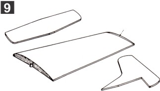
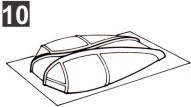
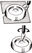
Cut two-piece bubble canopy from formed sheet with the point of a sharp blade (FIG. 7). Cement the two halves together (FIG. 8). Cut the plastic nose cowl free from formed sheet (FIG. 9). Cut hole for nose bearing (FIG. 10). Cement canopy to top of fuselage.
Lightly sandpaper the wing, stabilizer and rudder frames. Cover both sides of stabilizer and rudder with single pieces of tissue - also bottom of wing frames. The top of wing frame is covered in two sections as shown above.
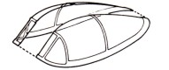
EXPLODED VIEW OF FRAMES
Note: frames should be tissue covered before assembly. Former "H" and instrument panels omitted for clarity.
Building the No. American T-28 Trainer