

|
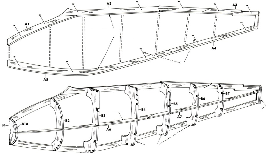
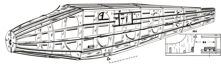
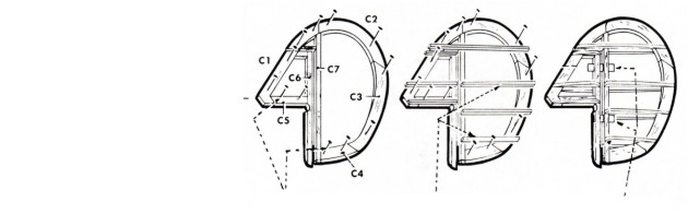
1. Pin to the center keel layout and cement to each
other keel parts A1 thru A5.
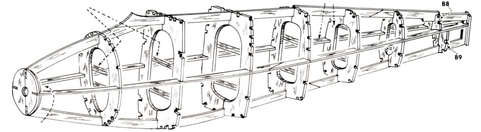
2. Cement the LEFT half formers to center keel making sure they are at right angle to keel. Cement one of the A6/A7 side keels into, the deep notches in the half formers.
3. When dry, remove frame from layout then cement RIGHT half formers to both center keel and left hand formers using the temporary alignment
|
sticks to exactly line up the right hand ones with those on the opposite side of the keel. Cement remaining side keel in place. For a rubber powered model see important note above!
4. Cement the 1/16" sq. stringers into the former
notches forward of B3. Cement the 1/16"x1/8" stringers into the notches from B3 back to the tail of the fuselage - refer to side view plan and above perspective. Attach stringers in pairs, one on one side then a corresponding one on the opposite side.
|
This will prevent a warping of the fuselage frame. For sharp bends, soak stringers in warm water first. They can be cemented in place while damp or wet. Add the strut wire retainers as shown above.
5. When dry, lightly sand fuselage frame to remove any balsa fuzz or excess cement. Prepare and attach the wire landing gear and vinyl structure shown on the back of plan.
Copyright 1987 by Paul K. Guillow, Inc.
|
|
Although clear and colored dopes have for years been mainstays for finishing tissue covered models, new techniques have been developed that permit the use of non-toxic liquids for the purpose. See supplementary information furnished with kit suggesting "white glue" as a tissue sealer and water based paint for color finishes which are inherently "fuel proof".
After a sealer has been brushed on the tissue and allowed to dry, proceed as follows: Paint all of the edges first then paint one half of the
|
fuselage at a time starting at the nose and proceeding to the rear.
Next, paint the top and bottom of one wing panel and stabilizer-elevator and one half of the fin-rudder. When dry, so you can handle the model, paint the remaining half. On the fuselage, brush on all coats the length of the fuselage. On the wing and tail surfaces, brush each alternate coat on in opposite directions, finishing with the last coat running in the same direction as the fuselage.
|
|
If the model has been built without movable control surfaces, the divisions between fixed and movable wing and tail surfaces should be laid out on the painted parts. Use either a ruling pen, blade ink and a straight edge to draw the outlines or cut the black lines bordering this instruction sheet and cement them in the appropriate locations.
|
Apply decals to model in positions shown following instructions on back of decals. Add finish details such as pitot tube, fuel tank vents, wire handles, etc.
If model has been built for rubber powered flying, see the special instructions for balancing, test flying and flight corrections provided on the front of plan in the area designated "Rubber Powered Free Flight".
|
|
Before starting construction of your model, study the plan and construction procedure carefully so that you will have a complete understanding of the step-by-step method of building this airplane. Guillow engineering has provided you with the most up-to-date method for building a real scale flying model.
Only careful attention to detail will insure the
|
success of your efforts. Most prize winning models are the result of patience and careful workmanship. You too, can achieve success by following the example of champion model builders—by working SLOWLY and CAREFULLY at all times. If you plan to build this model as a rubber powered flyer, simply follow the instructions shown on direction sheet.
|
Materials furnished for converting to U-Control - see the special instructions shown on the plan. The basic model construction is similar to the rubber powered version, but the special construction details required for U-Control Flying should be made during assembly as per the specific instructions given on the plans.
|
|
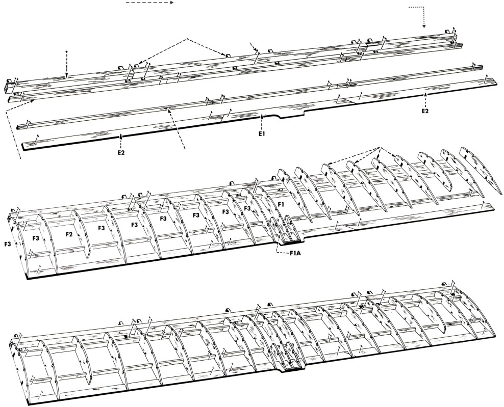
1. Pin E1 to wing layout. Cut the two E2's from strip stock then cement them to E1 pinning them over layout as shown. Cut and pin the leading edge and the top main spars to layout cementing the segments where jooined as shown on plan. Note shims under edge.
2. Cement ribs to leading edge, trailing edge and main spars line up carefully
|
3. The drawing shows all ribs cemented in place
4. When dry, cut and cement the 1/16" sq. multiple spars in notches on top of ribs. Join spar lengths as indicated on plan. Cement aileron separators MA1 in place between ribs and against top spar.
5. When dry, complete assembly of ailerons then remove frame from layout. Add single bottom spar.
|
Using modelers knife, shape and sand the leading edge to blend with ribs as shown by wing section drawing on plan. Lightly sand frame to remove any balsa fuzz or excess cement. Finally, cut the ailerons free of the main frame, cut and test fit the plastic hinges then set the ailerons aside for tissue covering.
|
|
If building a free flight flying model (rubber or gas powered), "dihedral" should be built into the right and left wing panels for flight stability as described on the opposite side of this |
instruction sheet. The Spirit of St. Louis had a "straight" wing with no dihedral. Build the frame this way for display purposes. |
|
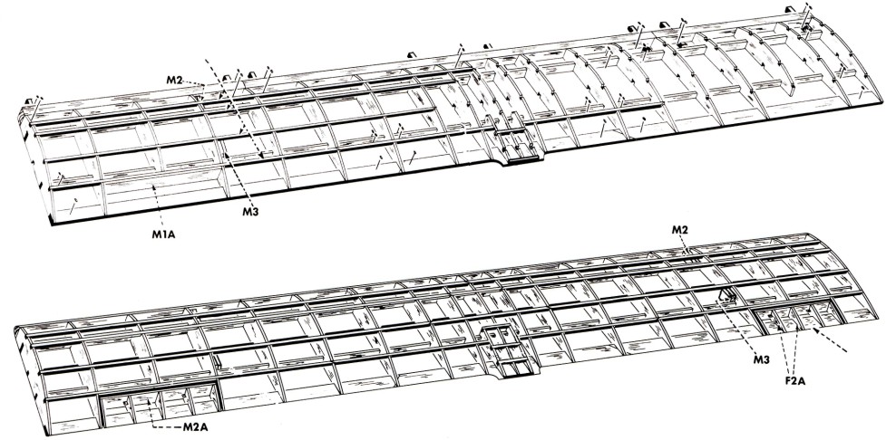
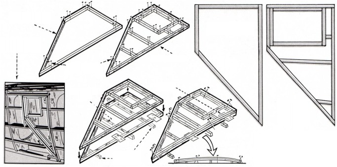
1. Select the F1, two F1A and two of F3 ribs and widen (or add) 1/16" sq. spar notches as per the three rib patterns shown above. Cut a wing rib angle gauge from balsa sheet stock. |
2. Working over the wing layout on plan, cut and pin the leading edge, trailing edge and main spars in position. The leading edge and main spars are one piece lengths from the wing tips to the center panel that
|
|
butt against separate short lengths in center panel area. DO NOT cement together Cut thru the trailing edge at locations indicated by the arrow heads.
3. Pin the wing rib angle gauge to layout, then, leaning one of the F3 ribs against it, cement the rib to the leading and trailing edges and main spars. When dry, add the remaining F3 rib in similar manner using the same wing rib angle gauge. Proceed to add all other ribs as shown by the drawings under Building The Wing Frame.
|
4. When dry, remove only the pins holding the right and left wing panels to the layout (the center panel parts remain pinned in place). Carefully raise the right and left wing tips to given dihedral height - block in position with anything available.
5. Cement the right and left wing panel parts to the center panel parts and let dry hard.
6. Finally attach all the 1/16" sq. multiple spars interlocking them in the center panel area as shown.
|
|
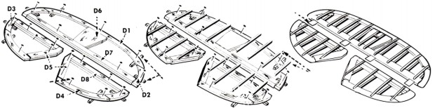
1. Starting with the double die-cut parts D5, D6, D7 and D8, cement them together in pairs, then, cementing them to each other, pin over the plan layout. Next add the single D1, D2, D3 and D4 outline parts noting the 1/16" sq. shims under each part.
2. Cut and cement the 1/16" sq. risers to the top of all D parts except D6.
When dry, remove frame from layout and add the
|
bottom 1/16" sq. risers.
3. Using sandpaper sand the frame so that all parts blend with each other as indicated by section X-X on the plan.
4. Finally add the 1/16" sq. strips that are cemented on the top and bottom of D6 then cut and test fit the plastic hinges that hinge the stabilizer and elevators together.
|
|
After sanding frames smooth, "size" all outside surfaces with either clear dope (cut 50% with dope thinner) or white glue mixed 70% glue, 30% water. This will fill the wood grain. Apply a minimum of two coats lightly sanding between coats and after the
|
final coat.
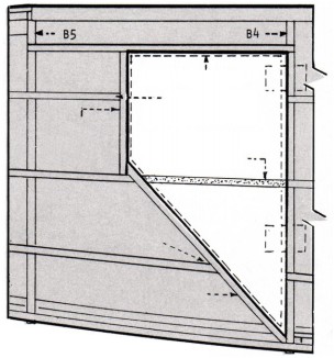
The above drawings show the areas of frames that can be covered with single pieces of tissue. Always cut tissue slightly oversize then "dry fit" (continued)
|
|
(continued) to see that "fits are smooth and not "puckered" at the edges. If wrinkles occur, cut tissue into smaller sections to avoid unsightly creases in the finished job
Fuselage. Using the same mixture for adhesive as used to size the wood, cover both sides in three sections shown by drawing above starting at former B3 and working towards the tail. (The tissue grain runs with the width of the tissue as received in kit.) Cover the top and bottom of fuselage in a similar manner.
|
Wing. Being a straight, non-tappered frame, it can be covered, top and bottom with large sections of tissue as shown.
Tail surfaces. These five separate frames can also be covered, top and bottom with single piece of tissue.
After frames have been tissue covered, wet all surfaces with fine spray of water using an atomizer if available. As a substitute, a wet paper towel can be used to apply moisture to the tissue. When the tissue dries out it will shrink tightly to the frames.
|
|
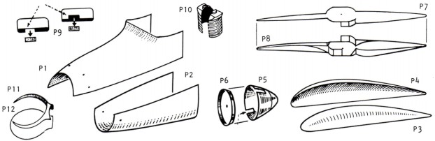
Step-by-step illustrated instructions describing cutting of plastic parts are furnished on one of the pages of the advertising folder included with kit.
|
Detailed instructions for cementing and painting the vacuum formed plastic in Guillow kits are furnished in the same advertising folder.
|
|
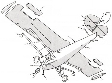
OPTIONAL: Although painting instructions follow model assembly, it is easier to paint the separate parts of The Spirit of St. Louis BEFORE assembly because of the interlocking wing and landing gear structures.
ASSEMBLY: Attach plastic cowl halves P1 and P2 to formers B1 and B3 and side keels A6. Attach P2 first then add P1 which overlaps P2 1/16". When
|
attaching a cowl half, bead the inside edges and the balsa contact areas with plastic cement the immediately set the part in position lining it up carefully before cement dries - wipe off any excess adhesive.
Next, cement the stabilizer-elevator to the fuselage and then cement the fin-rudder into place. Line up carefully, pin if necessary (continued)
|