
|
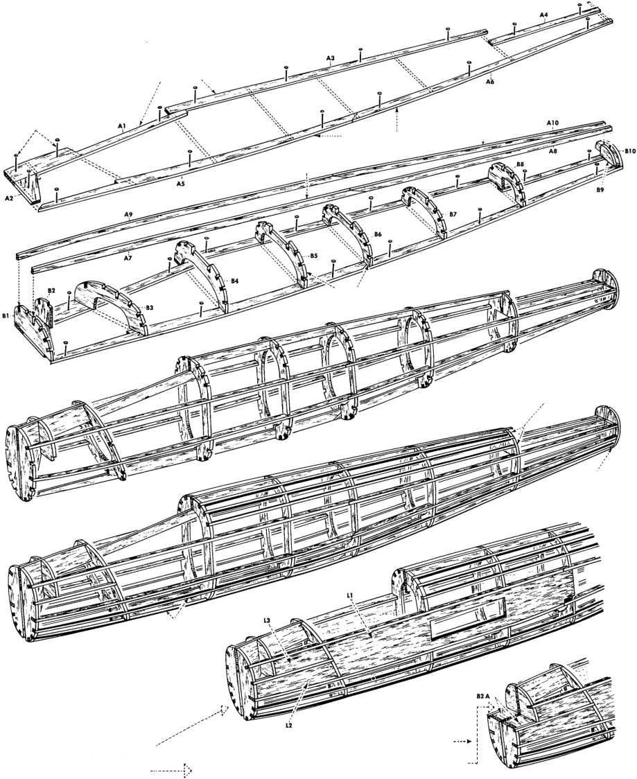
1. Pin the top and bottom keel parts "A1""A4" "A5" to plan. Cement "A2" "A3" "A6" together and pin to plan.
2. Cement one each of formers "B" into position on keels—be sure formers are at right angles to the keels "A." Cement side keels "A7" and "A8" "A9" and"A10" into deep notches of formers "B."
3. When dry, remove the frame from plan. Cement the opposite halves of formers "B" to center keels
|
and to formers "B" already in position. Cement opposite side keels into position.
4. Cement the 3/32" square stringers into their respective notches. "Refer to side view of model and fuselage perspective as an aid to stringer locations." To obtain uniform tension on fuselage during this stage of construction, cement the stringers alternately to the left and right sides. If certain stringers show too much
|
tension, soak the stringer or stringers in warm water for a few minutes to "limber up" the fibers and they will follow "bold bends" with ease. Cement all "L" parts into place.
5. Lightly sand fuselage to remove any balsa fuzz and excess cement.
|
|
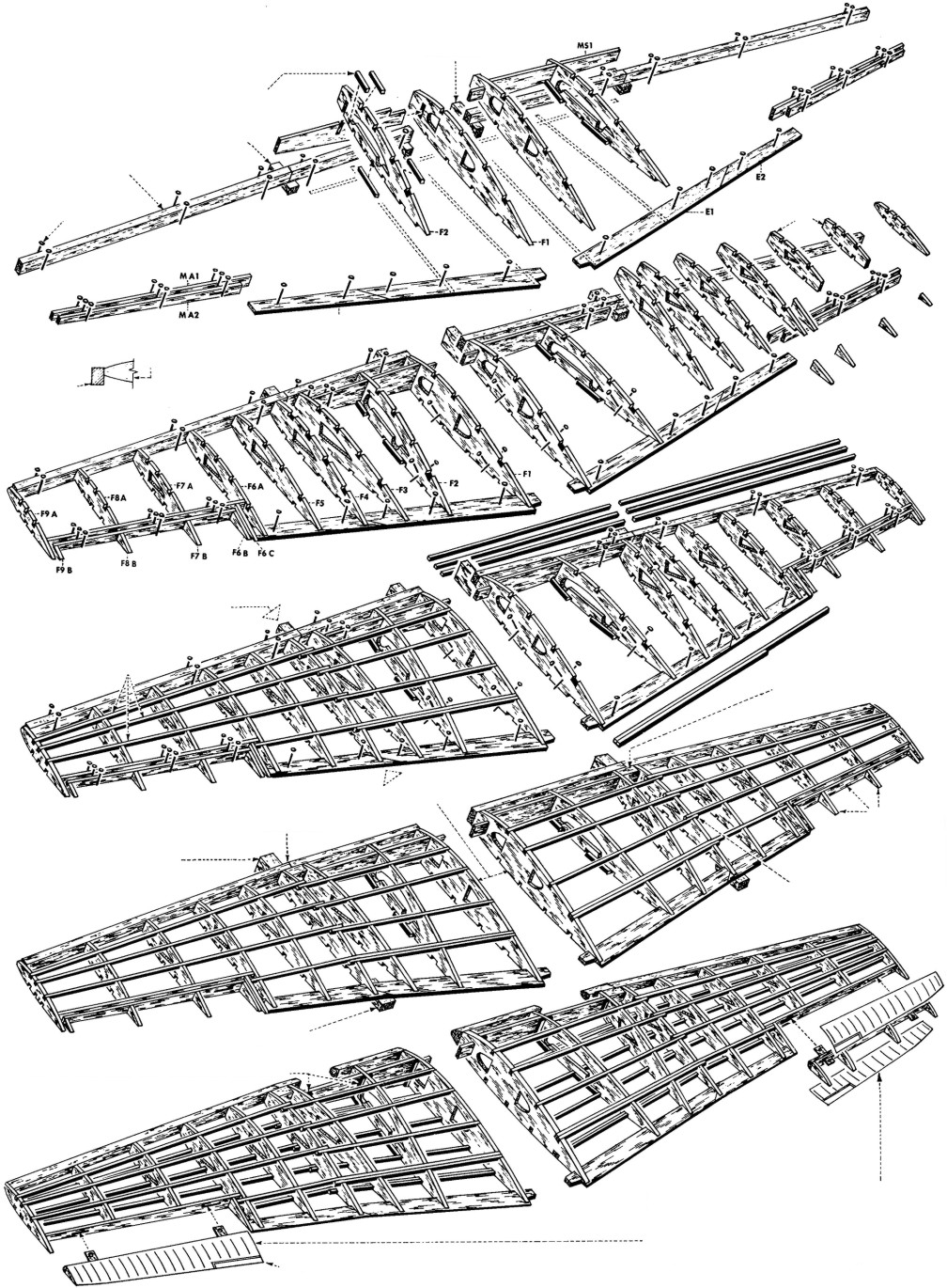
1. First assemble and cement the wing center section together. When completed, pin in place over the wing layout.
Pin leading edge and trailing edge to plan. Do not cement these parts at the dihedral joints at this time.
2. Cement all ribs "F" into position between leading and trailing edges. While wing is in this position,
|
cement all the top 3/32" square multiple spars into position on left and right wing. Do not cement these parts at the dihedral joints at this time.
3. When dry, raise and cement together the left and right wing leading and trailing edges. Cement "lap jointed" multiple spars into place.
4. When thoroughly dry, remove wing from plan
and cement the bottom 3/32" square wing and center
|
section multiple spars into place, also using the lap joint. With a razor blade or modelers knife, shape the leading edge to blend with the ribs as shown on the typical rib section drawing. Blend the leading edge into the tips and round the tips and trailing edges.
5. Lightly sand the wing to remove any balsa fuzz and excess cement.
|
|
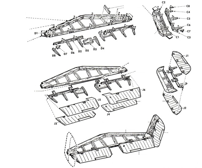
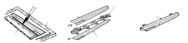
1. Pin to plan and cement respectively to each other all of the "D" stabilizer — elevator parts. Cut to size and cement spars and cross members into place.
|
2. Build the fin-rudder frame in similar manner using"C" parts and members.
3. When dry, remove the frames from plan and round all edges. Sand lightly to remove fuzz and excess cement.
|
|
Before starting construction of your model, study the plan and construction procedure carefully so that you will have a complete understanding of the step-by-step method of building this airplane. Guillow engineering has provided you with the most up-to-date method for building a real scale flying model.
|
Only careful attention to detail will insure the success of your efforts. Most prize winning models are the result of patience and careful workmanship. You too, can achieve success by following the example of champion model builders—by working SLOWLY and CAREFULLY at all times. For converting to U-Control
|
model see the special instructions on the front of the plan. Note: the basic model construction is similar, but the special construction details required for U-Control must be made during assembly as per the specific instructions given on the plans.
|
IMPORTANT NOTE!
THE "J' MODEL INDICATED IN THE THREE VIEW DRAWING IS THE SAME AS SHOWN ON BOX COVER. THE DECALS PROVIDED CORRESPOND WITH THIS
EXPLODED VIEW
|
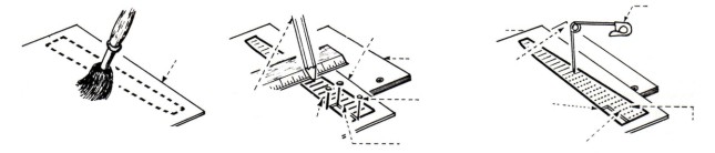
After all the frames have been sanded smooth, they must be "pre-doped" so that when you apply the tissue covering, the dope used to adhere the tissue to the frames will not be soaked up by the wood. This makes it much easier and faster to cover the model.
Because of the stringer and former construction, use a narrow ¼" or ½" wide brush to dope with. Use dope thinned out 50% with thinner to about the consistency of milk so it will brush easy and dry fast.
The outside surface of all stringers, formers, ribs, leading edges, trailing edges, spars and tips should be given at least three coats of clear dope at which time you will note that the doped surfaces will begin to shine a little. This shows that you have sufficient build up of dope on the wood. Lightly sand wood between coats of dope. There are two methods of covering a model with tissue. One is to cover with the tissue dry and the other is to cover with the tissue wet. When covering with dry tissue, smaller areas are covered at one time. Any area that is covered dry should be tried first to make sure it will not bunch up or wrinkle excessively before doping in place. The covering scheme shown on each plan is suggestive of dry covering. For dry covering, cut the tissue slightly larger than the area to be covered and after doping in place, trim excess tissue with a single edge razor blade.
Dry Covering the Frames
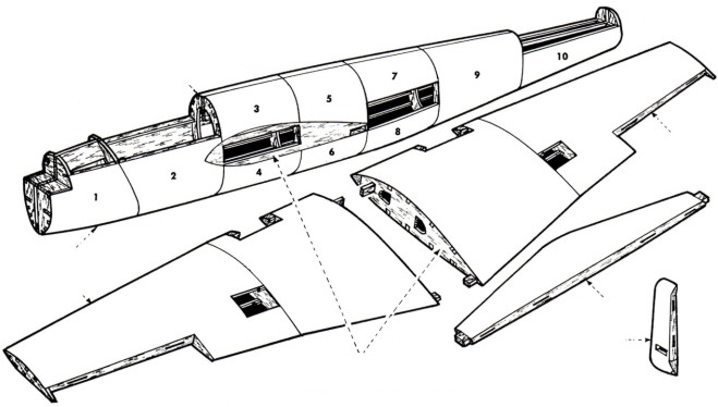
Fuselage: Cover the fuselage in sections as shown on scheme, starting from the front of former B1 and covering vertically between formers. The grain of the tissue should run lengthwise with the fuselage. (The grain of the tissue runs with the width of the tissue sheet as you receive it in the kit).
Wing: On straight tapered wings, you can cover the complete top and bottom of each wing panel between the dihedral break and the last tip rib with one piece of tissue. Use separate piece of tissue for top and bottom of the center section and the tips. Elliptical wings like the Spitfire must be covered with separate pieces of tissue between each rib and from leading edge to the trailing edge. The grain of the tissue must always run span-wise on the wing.
Tail surfaces: The top and bottom of each tail surface can be covered with one piece of tissue. The tissue grain should run
|
spanwise on the stabilizer-elevator, and vertical on the fin-rudder. After the frames are covered, they should be wet with water by using an atomizer or by using some of the tissue folded several times and used like a brush to lay the water onto the tissue. When the water has evaporated and the tissue has dried, the tissue will be taut. At this time, brush on one coat of dope over all of the covered parts.
Wet Covering the Frames
When covering with wet tissue, large and sometimes complete areas can be covered at one time. To prepare tissue for wet covering, cut tissue slightly larger than the area to be covered and either wet tissue under a faucet or in a pan with water. Have a face towel spread on the table — lay the wet tissue on the towel to rid of excess water and immediately proceed to cover the frame. Carefully lay the wet tissue over the area. Gently start drawing the tissue taut, not tight, in different directions, but always away and out from the center of the area. Work as fast as you can while the tissue is still wet or damp. You will note that the tissue follows compound curves because in wetting the tissue, you have relieved the tension on the fibers and they now will stretch a little. As soon as the tissue is smooth over the whole area, dope it on by doping over the wood areas only. The dope will go right through the wet tissue and stick the tissue to the wood. As the tissue dries, it will tighten up and the dope may turn white or "blush" at this time, but the blushing will disappear after the next coat of dope.
Areas to cover with wet tissue: Each vertical half of the fuselage can be covered in one piece from former "B1" to former "B6" and from former "B6" to the end of the fuselage. Each wing panel from the dihedral break out to the tip on the top or bottom can be covered with one piece of tissue. The top and bottom center section is covered with one piece of tissue. All surfaces of the tail can be covered with one piece of tissue.
After all frames are covered and dry, brush on at least three coats of thin dope or more, if necessary, until the tissue pores are filled and the tissue is starting to shine. Use a ½" to ¾" wide brush for doping. Sand with very fine sandpaper between coats of dope.
|
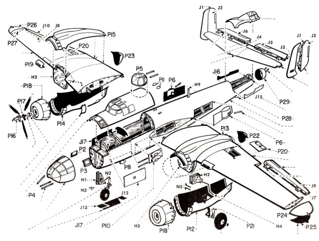
EXPLODED VIEW OF MODEL
|
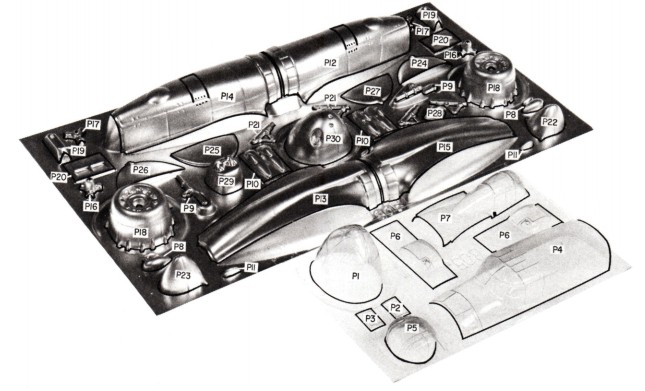
The formed pieces on the vinyl plastic sheet should first be cut apart with scissors. Using the point of a modelers knife or a single edged razor blade, score the plastic part as close as you can at the trim points. The score should be deep but not through. Score twice if necessary. After scoring, gently bend the excess material back and forth until it breaks away. Now sand all the edges to smooth them off.
Use a plastic cement for joining of any matching halves. (Refer to note on plan about adhesives and dopes for plastic parts.)
Sand finish joints after cement has dried. Except for any special cut-outs as mentioned in "Installation of Glo-Engine", the plastic parts are ready to be attached to the model.
|
Most dopes and paints will invariably tend to soften the plastic if too much is applied at frequent intervals. When painting over plastic, work fast and let each coat of dope or paint dry at least ½ hour.
The clear plastic canopy is made from acetate and is a different material than the other plastic parts. It is thinner and more easily softened than the vinyl plastic pieces. Extra special care should be taken when cementing the canopy in place and when painting in the window separation. If these suggestions are followed, you should have no problem with the attachment and painting of plastic parts thus insuring a neat appearing model.
|
|
Trim the plastic nose cone to shape. Refer to special instructions on "Plastic Parts Preparation". At this time, take the larger portion of the clay furnished in the kit and after making the clay soft and pliable by working it with your fingers, carefully press the clay into the inside front and bottom of the cone as shown in dotted lines on the side view of the model. Work the clay into position so that it fills the particular area. The remaining portion of the clay will be used later for final balance of the model.
Cement the plastic cone to the front former "B1" by first beading the immediate inside edge of the plastic cowl with cement and also beading around the edge of "B1" former. Slip the cowl onto the fuselage and after lining up the cone carefully, wipe off any excess cement. After the cement has dried, you will note that the edge of the cone has shrunk and blended itself into the fuselage. A light amount of sanding around the edge will smooth the joint.
Next, cement the stabilizer-elevator to the fuselage and then cement the fin-rudder into place. Line up carefully, pin if necessary until dry. Cement the wing to the fuselage. Line up
|
carefully and either rubber band or pin in place until dry. Trim and cement any and all other plastic parts such as radiators etc. into position — refer to plan for locations.
NOTE: To do a neat job of cementing plastic parts to the model, follow this procedure — first, locate the part on the model without cement and while holding it in position, with a very soft pencil, mark around the part and onto the model. Then when cementing part to the model, the part can immediately be positioned without guesswork. Plastic parts should be held in position until dry with pins or rubber bands. If the model is to be only a show model, then any cockpit detail you desire should be incorporated into the model. Also the inside of the cockpit should be painted a light green. After cockpit details are in place, trim the canopy as shown and cement into position on the fuselage. Follow the same procedure as used with other plastic parts.
The plastic spinner should be trimmed and cemented to the scale propeller. The model is now ready to be painted. Refer to special instructions on painting the model.
|
|
There are two types of fast drying colored dopes you can use on your model. One is Nitrate and one is Butyrate fuel proof. The Butyrate is fuel resistant but the Nitrate is not. You can also use a plastic base type paint finish (see your hobby shop dealer) that is also fuel resistant and fast drying. You can use any of these three types for the rubber and non-flying scale version of the model, but you must use a fuel resistant type if you use a glo-plug engine, because the potent materials in the fuel will soften and dissolve the nitrate dope. This, of course, will spoil your finish.
Generally, the colors on the war planes were of a dull or semi-gloss finish. Most of the dopes are a glossy paint. Ask for and use a paint that has an authentic dull finish and makes for real scale effect when used. The proper colors can be had by inter-mixing the paint colors. Also, the glossy paints can be used and dulled after they are dry by using an abrasive mixed with water, such as Bon-Ami powder. Rub the surface just enough to take away the high gloss and then wash the powder off with clear water.
The painted finish of your model will only be as good as your preparation. The consistency of the paint should be such that
|
it does not dry out while being applied and still not so thin as to run easily. Use a good ½"to ¾" brush and, assuming that the model is clear doped, smooth and clean, proceed as follows: Paint all of the edges first. Paint one half of the fuselage at a time starting at the nose and proceeding to the rear.
Next, paint the top and bottom of one wing panel and stabilizer-elevator and one half of the fin-rudder. When dry, so you can handle the model, paint the remaining half of the model. On the fuselage, brush on all coats the length of the fuselage. On the wing and tail surfaces, brush each alternate coat on in opposite directions, finishing with the last coat running in the same direction as the fuselage.
Apply only enough colored paint to give complete coverage, as colored paint is heavy. Usually, two or three coats is enough. When more than one color is required on a model, finish the lightest color first and the darker color last, because dark colors cover over light better than light over dark. Allow sufficient time between coats for the paint to dry.
|
|
After the model has been painted, ink in the control surface lines — refer to drawings for positions. Apply decals to model in positions shown following instructions on back of decals. Add finish details such as radio mast, struts, etc. The model can now be balanced at the point shown on the plan by
|
adding the necessary amount of clay to the front and bottom of the cone. Soften the clay and smooth it on so that it blends with the cowl area. In the event that the model is nose heavy without the additional clay, you can add small amounts of clay to the rear of the model.
|
NOTE: All wire parts coded N
All cardstock parts coded__ J
All plywood parts coded___ H
All plastic parts coded_____ P