


|
PREPARATION OF FUSELAGE FORMERS
Carefully remove all formers (F1 thru F12) from die-cut balsa sheets cutting them loose with the point of a model builders knife if necessary. Lay each former half over its respective template then, with a soft pencil, lightly mark the former number on the face of any half former whose printed number is concealed on the bottom surface.
All former halves are die-cut with 3/32" deep shoulders to match the 3/32" thickness of the center keel parts (A1 thru A4). All former halves that are to be glued to the pinned down center keel (the "shaded" ones on the layout are for left side of fuselage) are to be used with the 3/32" shoulders as die-cut. All of the matching former halves (for right side of fuselage) MUST have these 3/32" shoulders trimmed off so when they are glued in place, they will fit flush against the center keel & and left side formers. Use a straight edge and razor blade to carefully remove these 3/32" shoulders- see layout sheet.
|
The 3/32" sq. stringer notches in the half formers are only partially die-cut and, to clear them, the sides of the notches must be cut with the point of a razor blade or model builders knife. Pin each right and left half former over its respective template then finish the stringer notches as shown in drawing on Plan A.
FUSELAGE CONSTRUCTION
1. Remove all "A" and "F" parts from die cut sheets.
2. Pin and cement center keel parts A1, A2, A3 and A4 in place.
3. Lay parts F1 thru F12 (both halves) over layouts on plan and cut notches (see instructions near layouts).
4. Dry fit then cement in place formers F1- F12 left sides, (with shoulders) to the center keel. Make certain that the formers are cemented at 90 degree angles — see drawing above.
5. Pin side keel parts A5 and A6 to the side keel layout and cement together. Slightly score the "crack" line.
|
6. Remove side keel from plan and cement into formers.
Dry fit first if the side keel does not stay straight, slightly widen notches in formers so that the side keel remains straight. The side keel is "cracked" at F10 to bend up to F11 & F12..
7. Remove frame from building board and add the right halves of formers (without shoulders). Use alignment stick made from scrap balsa to keep formers straight while gluing - see drawing above.
8. Repeat steps 5 and 6 to the right half of fuselage.
9. Cement stringers in place, alternating stringer installation from right to left side of fuselage while gluing will ensure uniform tension and reduce the risk of warpage.
10. Lightly sand the fuselage to remove fuzz and to smooth the fuselage frame.
11. Cement A7 on top of stringer and behind F11 as shown above.
|
|
WING CONSTRUCTION
The right and left wing panels are similar and can be assembled individually or both at the same time if desired. The instructions that follow describe the wing center section then the right wing frame assembly, to assemble the left wing follow the right wing instructions for they are the same.
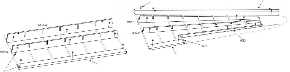
All wing ribs and related parts should be checked against the corresponding templates on Plan for accuracy of outline, stringer notch locations, size, etc. As with the fuselage formers, the 3/32" sq. stringer notches in the ribs are only partially die-cut and, to clear them the sides of the notches must be cut with the point of a modelers knife. Pin each rib over its respective template then complete the spar notches as shown - see drawing on Plan A. The long pre-cut notches in the ribs that mate with those in the main spars (MS1-A & B and MS2-A & B parts) should permit these parts to slip together without undue force that might result in breakage.
Test fit the ribs and main spar notches together before starting frame assembly and, if any notch is too tight, widen slightly with a modelers knife. Aim for a smooth fit, not a loose fit.
It is recommended when assembling the wing frames, that the forward end of the ribs for the right and left wing frame panels be given a slight taper with sand paper to conform to the slant of the leading and trailing edges. Do not shorten ribs when sanding - a slight taper is sufficient.
|
BUILDING THE WING CENTER SECTION
1. Remove CENTER WING parts from die cut sheets. Lay wing ribs and MS1-A over plan layouts and cut notches, the rear of the notch has already been cut for you.
2. Cut to size & pin in place the trailing edge (3/16" x 1/2").
3. Pin MS1-A and MS2-A in place over plan.
4. Dry fit the seven center section ribs. When ribs fit smoothly, glue to trailing edge, MS1-A and MS2-A.
5. Place 3/32" sq. shims under leading edge (1/4" x 1/2") and glue leading edge to ALL ribs W1 and W2.
6. Cement the two fillets in place.
7. Dry fit, then glue the top stringers in place.
8. When all glue is dry, remove frame from plan and cement bottom stringers in place.
9. Glue W2B's in pairs, then glue into place against MS1-A and W2.
10. Sand completed center wing section to basic shape (80 grit sandpaper), then sand to finished shape (220 grit sandpaper).
BUILDING THE RIGHT WING FRAME
1. Remove RIGHT WING parts from die cut sheets. Lay W1 thru W10 over wing rib layouts on Plan and cut stringer notches.
2. Pin MS1-B and MS2-B to plan.
3. Cut to size and pin the leading edge (1/4" x 1/2") in place making sure to place the 3/32" shim under leading edge where indicated on Plan.
4. Cut trailing edge (3/16" x 1/2") to size and pin in place, glue W11 to trailing edge and glue MS3 to W11, pin in place.
5. Dry fit ribs W2 thru W10. Sand the leading edge of the ribs slightly to conform to angle of leading edge. When correct
|
glue ribs in place (to leading edge, trailing edge, MS1-B, MS2-B and MS3).
6. Glue the three wing tip blocks together, when dry, glue tips to W10, MS3 and leading edge.
7. Glue top stringers in place.
8. Glue the three fillets in place. - W12 against W2 and leading edge, W13 against W2 and the trailing edge and W14 against the trailing edge and W11.
9. Glue the three aileron pieces together (short one on top). When dry, pin in place and glue scrap balsa shims where shown to hold aileron in position while sanding to shape.
10. Remove wing frame from plan and cement bottom stringers in place
11. Sand wing panel / aileron to shape. Use coarse sandpaper (approx. 80 grit) to work piece down to basic shape, then use fine sandpaper (approx. 220 grit) to sand to finial shape. Note: A large sanding block (3" x 6" x ½") will help you in sanding uniform surfaces. See cross section on Plan for final shape. When sanding top of wing it is easier to place on a table top along the edge and sand the top surface of the wing and aileron while the whole surface is supported by the table.
12. Carefully remove the scrap balsa shims that were installed in step #11.
13. Slightly round over the edges of parts MS3 and the leading edge of the aileron to allow free movement of aileron.
14. Using a modelers knife, cut the hinge slots for hinges in parts MS3 and aileron (location shown on Plan). Cut three 1/4" x 3/8" hinges out of clear plastic material supplied in kit. Dry fit the hinges.....Do Not glue in place until after covering the wing frame.
Build LEFT WING using same instructions!
|
|
MODEL BUILDER - Before starting construction of your model, study the plan and construction procedure carefully so that you will have a complete understanding of the step-by-step method of building this airplane. Guillow engineering has provided you with the most up to date method of building a scale static display model. Only careful attention to detail will ensure
|
the success of your efforts. Most prize winning models are the result of patience and careful workmanship. You too, can achieve success by following the example of champion model builders - by test fitting your parts before gluing and working SLOWLY and CAREFULLY at all times.
|
Propeller
|
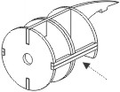
PROPELLER ASSEMBLY CONSTRUCTION
1. Remove propeller blades from die cut sheets.
2. Glue 1/16" scrap balsa fillers onto the "base" of the propeller (see above).
3. Sand propeller blades - sand propeller blade to airfoil shape and propeller base to round shape to fit into prop hub.
|
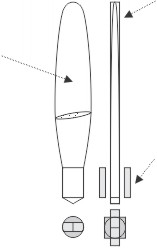
4. Score and remove parts P19 Spinner and P18 Half Hubs from plastic parts sheet.
5. Glue two plastic Half Hubs together. When glue dries, sand off any excess. Drill hole through center for prop hook.
6. Insert propeller blades into hub at a slight angle and glue.
|
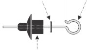
7. Place Lock Washer and Nose bearing onto Prop Hook.
8. Insert Prop Hook through Hub and place a Lock Washer
on the end. Glue both lock washers to Prop Hook.
9. Glue plastic Spinner P19 to the front of Hub.
10. Insert propeller assembly into N5 on the nacelle.
|
|
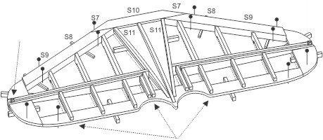
STABILIZER / ELEVATOR CONSTRUCTION
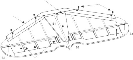
1. Remove all "S" parts from die cut sheet. (draw on both sides of S1 the location of S10)
2. Pin on plan and glue together parts S1, S2 and the two S3's. Glue together FLAT without shims.
3. Cut and glue 3/32" rib cores to S2.
4. Cut, pin on plan and glue the three 1/4" x 3/8" leading edge pieces to each other, on the FLAT without shims. DO NOT glue leading edge to S1 at this point!
5. When cement is dry, lift up leading edge and slip 1/16" shims under leading edge where shown on plan. Pin leading edge in place.
6. Lift up trailing edge assembly (S1-S3 & rib cores) and place 9/64" shims (die cut) under trailing edge where shown on plan. Pin trailing edge in place. (place 9/64" die cut shims over pattern on plan to check size if over size trim to correct size)
7. Place S5's on plan and glue to S3 and 3/32" rib cores. Be careful to glue rib cores to the middle of S3. Pin in
place
|
8. Bevel the ends of (both) S6's to fit snugly against S1 and cement to S1. Pin in place (Caution! Bevel and fit one at a time to prevent beveling at the wrong angle)
9. Place S4's on top of 9/64" shims and glue to S6 and leading edge.
10. Bevel the leading edges of parts S7, S8 and S9 to fit against leading edge, cement to the leading edge and S6 making sure that S7, S8 and S9 are aligned even with the top of S6.
11. Glue S10 and two S11's to the top of S1 and against leading edge.
12. Glue 3/32" x 1/8" pieces on top of rib cores, making sure to glue them to S5 and S2.
13. Slide a piece of scrap balsa between the tips of S5 and S6 and lightly glue in place (see above). This is to keep the elevator in place while sanding the airfoil shape.
14. When all glue is dry, remove the stabilizer/elevator from plan. Repeat steps 11 and 12 on the bottom of the stabilizer / elevator.
15. Trim off risers on parts S5 - S9.
16. Draw a center line along the outside edge of the 1/4" x
|
3/8"
leading edge with pencil. This will assist you in sanding a smooth and accurate
leading edge.
17. Sand stabilizer / elevator to shape. Use coarse sandpaper (approx. 80 grit) to work piece down to basic shape, then use fine sandpaper (approx. 220 grit) to sand to finial shape. Note: A large sanding block 3" x 6" x 1/2" will help you in sanding uniform surfaces. (See cross section for finial shape)
18. Carefully remove the scrap balsa shims that were installed in step #13. Using a modelers knife cut S2, separating elevator from stabilizer, see location on plan.
19. Slightly round over the edges of parts S5 and S6 to allow free movement of elevator.
20. Using a modelers knife, cut the hinge slots for hinges in parts S5 and S6 (location shown on plan), Cut four 1/4" x 1/2" hinges out of plastic hinge material supplied. Dry fit the hinges, DO NOT glue in place until after covering.
|
|
FIN / RUDDER CONSTRUCTION
1. Remove all "R" parts from the die cut sheets.
2. Pin to Plan and glue together parts R1 thru R7 to form the first layer of the rudder.
3. Glue parts R8 thru R15 on top of and to R1 thru R7. Use pins around the R1 - R7 structure to align the second layer (see drawings above).
4. Mark the location of strip stock on R8 with a pencil.
5. Cut to length and glue in place all rib cores. Cut the rib cores from 3/32" x 3/16" stock.
6. Remove the structure from the plan and glue strip stock,
|
ON BOTH SIDES, over the rib cores and parts as indicated above.
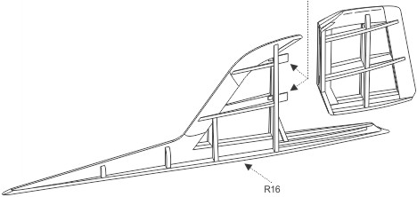
7. Glue R16 on the bottom of the Fin assembly. HINT: Glue R16 to the front and back first, then bend up slightly and glue the middle. It should NOT be straight as this slight bend matches the back of the Fuselage.
8. Sand the Fin / Rudder assembly to shape. Use a coarse sandpaper (approx. 80 grit) to work the piece down to the basic shape, then use fine sandpaper (220 grit) to sand to the final shape. See the cross section drawing on the Plan for Fin / Rudder shape.
9. Cut R3 and R4/R12 where indicated above and on Plan t
|
to separate the Rudder from the Fin. Sand off any excess balsa where you cut to make it a smooth finish.
10. Slightly round over the edges of the strip stock on parts R6 & R14 to give the Rudder freedom of movement.
11. Using a modelers knife, cut the hinge slots for the hinges. Cut two 1/4" x 3/8" hinges from hinge material supplied and dry fit into Fin / Rudder. DO NOT glue in place until after covering.
|
Nacelles
|
NACELLE CONSTRUCTION
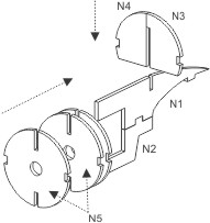
1. Remove parts N1 thru N5 from die cut sheet.
2. Pin FLAT over Plan layout and glue together parts N1 and N2.
3. Pin FLAT over Plan layout parts N3 and N4 and glue. When glue is dry, lift up and glue to N1/N2 structure.
|
4. Glue together two N5's to create a double thickness former and slide onto N1/N2 - Glue in place.
5. Glue a single N5 on the end on the N1/N2 structure.
6. Glue two 3/32" stringers on both sides of nacelle.
7. Repeat steps 2 - 6 to make a duplicate nacelle.
8. Place nacelles onto center wing frame, making sure that the nib in the back of the nacelle structure fits into the
|
notch in MS1-A (to ensure proper placement). AFTER tissuing the center wing panel, glue the nacelles to leading edge and MS1-A
|
Landing Gear
|
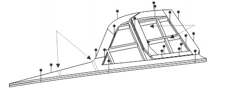
The model frames can be covered either with the tissue supplied in this kit or with the new lightweight iron-on films available at most hobby dealers. No pre-priming or painting is required when iron-on films are used. Instructions for applying this material is supplied by the manufacturer. The instructions that follow pertain ONLY to a tissue covered model.
The drawings above show the frames after being tissue covered. It is important to note that many of the photographs that are on these plans show the frames without tissue covering. Nonetheless, all frames should be covered as illustrated above because it is extremely difficult to apply tissue covering to the framework of an assembled model.
A mixture of white glue (such as Elmer's Glue-All) and water makes an acceptable adhesive for the tissue covering of model frames. 40% glue / 60% water solution is excellent for this purpose. Use a 1/4" or 1/2" wide brush for applying this adhesive.
This 40%-60% mixture can be used for three different purposes: 1. As a primer coat over balsa wood before applying tissue. 2. As an adhesive when covering a frame with tissue. 3. As a primer over the tissue covered frames to act as a base for the application of the final waterbased color coats. Two or more coats of "primer" applied with a 1" wide brush should do the job. These primer applications will cause the tissue to sag noticeably when applied but, as it dries, it will shrink taut.
Of course, clear model airplane dope, the old standby, is still the better method, but it is a second choice because of its chemical composition. If
|
clear dope is used, thin out 50% with dope thinner so that it will brush out smoothly and not dry too fast.
Before starting to cover the fuselage, cut out the vacuum formed plastic nose cone and test fit it over former F1. If the fit is a bit too snug, sand around the former perimeter until the cone slips in place. Now set the nose cone aside until later.
Refer to Photos 10 thru 16 on the General Information Sheet for using a glue/water adhesive mixture. Be sure that all frames are sanded smooth before starting to apply tissue covering.
Cover the fuselage in sections as shown above, starting from the front or former F1 and covering vertically between formers. The grain of the tissue should run lengthwise with the fuselage. (The grain of the tissue runs with the width of the tissue sheet as you receive it in the kit).
Wing: Cover the top and bottom of wing frames in sections shown by line drawings. The grain of tissue must always run span wise on the wing.
Tail Surfaces: The rudder/ fin can be covered with four sections of tissue - two on each side for fin and rudder. The stabilizer is covered in sections as per drawing - tissue grain should run span wise.
After the frames are covered, the covering should be wet with water by using an atomizer (spray bottle) or by using some of the tissue folded several times and used like a brush to lay the water onto the tissue. When the water has evaporated and the tissue has dried, the tissue should be taut. At this time apply the final primer coats of the white glue/water mixture
|
|
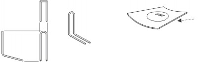
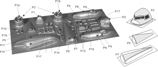
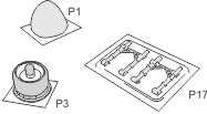
Before using the vacuum formed plastic parts, wash them with soap and water to remove any trace of lubricant used for molding the parts. Any lubricant on a part will mar the finish when paint is applied later on.
The plastic parts should be lightly numbered with a soft lead pencil then cut apart with a pair of scissors (see above for part identification). Two pages of the enclosed "Balsa Model Kit Catalog" is devoted to the cutting, cementing, and painting of Guillow vacuum formed parts. If not familiar with these techniques, it will pay to read the information supplied before cutting out the parts.
Using the point of a model builder's knife or a single edged razor blade, score the plastic as close as you can at the trim points. The score should
|
be deep but not through. Score twice if necessary. After scoring, gently bend the excess material back and forth until it breaks away. Now sand all the edges smooth. The plastic parts are now ready to be attached to model frames. Use a plastic cement when joining the matching halves of parts that require joining before being added to the model. After the cement has dried, lightly sand the joints to a smooth finish. The plastic parts are glued to the tissue covered frames BEFORE the frames are painted and assembled. Use contour putty to fill any gaps between the matching halves or between the plastic part and model frame work. (Contour Putty is available at most local hobby shops).
|
|
Tissue covered frames and plastic parts can be painted with water based acrylic paints available at a local hobby shop. It is easy to apply, has good coverage and can be cleaned up with plain water - especially for cleaning brushes, spilled drops, etc. Of course, regular model airplane dope can be used for painting purposes but we consider water based acrylic colors "safer" and easier to apply and use them in our model development work.
Generally, war plane colors had a dull finish and can be purchased at most hobby shops. Follow the manufacturer's instructions when using water based acrylic paint. Use a good ½" to ¾" brush and proceed as follows: Paint one half of the fuselage at a time starting at the nose and proceeding to the tail. Next paint one side of each of the wing
|
frames, stabilizer, and rudder. When thoroughly dry, paint the other side of each unit.
On the fuselage, brush on all coats the length of the fuselage. On the wing and tail surfaces, brush each alternate coat in opposite directions, finishing with the last coat running in the same direction as the fuselage. Apply only enough colored paint to give complete coverage, usually two or three coats is sufficient. When more than one color is required, finish the lighter color first and the darker color last, because dark colors cover light colors better than light over dark. Allow sufficient time between coats for the paint to dry.
After the model parts have been painted add the panel lines, door lines, etc. (permanent pen or thin black tape).
|
|
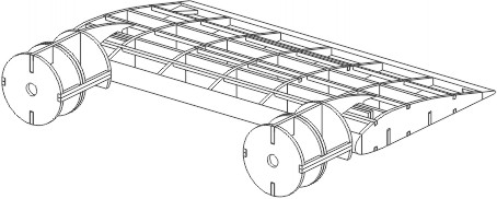
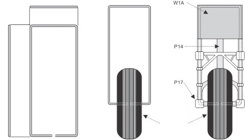
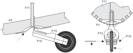
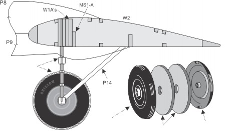
Although the assembly photos show "uncovered" frames, all should be tissue covered PRIOR to assembly unless building a model with a "skeleton" framework.
After the plastic landing gear (P17) is glued around the main landing gear fit into wing. If the fit is too tight, sand the W1's to reduce their thickness. When fit is snug, cement in place.
Cut out the cardstock wheel wells (J1) and crease and fold the parts as indicated taping on unprinted side if necessary. Insert these parts into their respective openings and test fit before gluing in place.
Glue the plastic yoke part (P14) to P17 and to the rear of the lower engine nacelle.
Now refer to "Propeller" section on the Building Instructions plan. Make the two propellers required as per instructions provided.
|
When completed, glue the printed dummy motors (J2) to the forward N5 of each nacelle. Make sure the engine cowls P3 have been glued in place before gluing the nose bearing to N5.
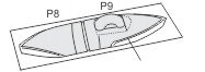
Next glue the plastic fillets A7 to the fuselage tail then glue the stabilizer on top. Add the wood fillet A8 to the top of the stabilizer to support the fin / rudder. Glue the rudder to the top of the stabilizer and fuselage - line up carefully. Add the tail fairing (P6 and P7).
Glue the right and left wing panels to the center wing section - BE CAREFUL as this glue joint determines the dihedral of the wing. Attach the completed wing to the fuselage (on both sides). Add the wing fairings, parts P10 and P11.
Finally add the "finishing details" such as decals, wheel wells, windows, wing lights, nacelle skirts and antennas, etc.
|
ACCESSORY PARTS (OPTIONAL)