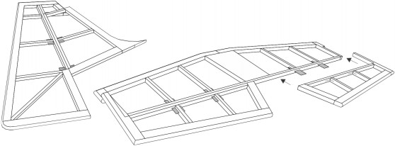
BUILDING STABILIZER AND RUDDER FRAMES
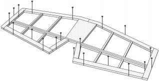
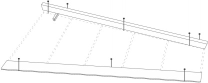
1. Place a 5/32” shim (3/32” + 1/16” scrap balsa stacked) under leading edge. Cut 3/16” x 3/8” leading edge stick to size over plan. Place and pin the leading edge and W1 trailing edge into place over plan.
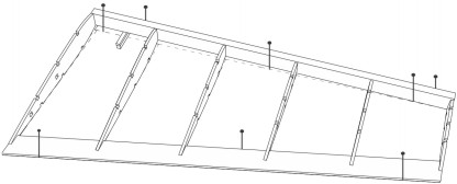
2. Cement wing ribs W2-W7 into their positions between leading edge and trailing edge.
NOTE: If building a flying model use the WA piece to create the correct angle of W2, with sets the wing dihedral.
3. Cement the top three 1/16” spars into position.
4. Cut 3/32” square sticks to 2” and glue into place into the square slots in W2, making sure that their ends land on the + on W3 to ensure correct placement.
5. Remove from plan and cement the bottom 1/16” spars into position.
6. Follow the same procedure in assembling the opposite wing half.
7. When dry, remove wing frames from drawing plan. Using sandpaper sand the leading and trailing edges to shape and gently smooth all other surfaces.
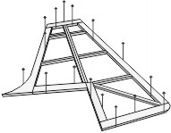
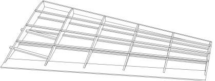
1. Pin to plan and cement respectively to each other, all rudder parts “R”.
2. Cut the 1/16” x 3/32” spars to size and cement into position.
3. The stabilizer is built in similar manner as above, using “S” parts.
4. Sand the pieces to remove all fuzz, bumps and excess glue.
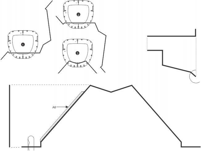
The numbers in circles show the
order you should build the structures.
Will this model be for static display of for flying? If you are building a flying model be sure see section D on the back side of
this plan and use enlarged FLYING STABILIZER LAYOUT and “SF” parts, which are 115% over scaled for more stable flying.
Do you want fixed or movable tail surfaces? If you choose to build movable surfaces
you will need to make hinges from scrap material and be sure not to glue parts
together along the hinge lines (see further notes below). Hinge location
shown on layouts below but gone into more detail in section D.
IMPORTANT questions to ask yourself BEFORE starting to build the stabilizer and rudder!
Plan and Instruction Sheet
JUST FOLLOW THE STEP-BY-STEP NUMBERS
FOR BUILDING EACH FRAME AND YOU’LL
AVOID ASSEMBLE ERRORS.
The frames for this model are assembled directly over the full size layouts printed on this side of the plan. The plan has been divided into easy-to-read work sections and it is suggested that, starting with area A , you complete the frames in one area before starting the next frame project.
Although the frames are built directly on the layouts the plan MUST first be laid flat on a workboard and covered with wax paper to prevent frames from sticking to it during assembly. For a workboard, use corrugated cardboard, soft wood, Celotex ceiling tile, etc. any flat surface into with you can easily stick common pins.
The model frames are built from balsa sheet parts and strip stock. Parts on the sheet stock are laser cut and lettered to correspond with the letter on the plan (R1, R2, R3, etc.) The strips (for stringers, spars, etc.) are to be cut to various lengths as needed while building.
TOOLS AND ACCESSORIES REQUIRED
In addition to the contents of this kit, you will need the following tools and accessories: model airplane cement, white glue, 1/4” wide paint brush, model knife and fine sandpaper, all of with can be obtained at your local hobby store. Also required and usually found at home are common pins, wax paper, a single edge razor blade and if you are building your model with movable parts an aluminum soda can to make hinges.
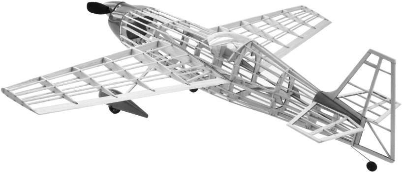
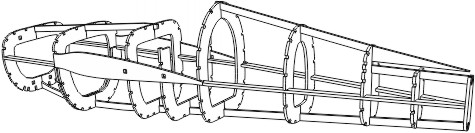
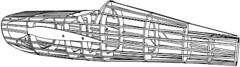
DETAIL OF AIRPLANE
FRAME WORK
NOTE: ALL FRAMES
COVERED WITH TISSUE
BEFORE ASSEMBLY!
IMPORTANT PRE-WORK INFORMATION
Be sure and let the cement dry
HARD before removing frames
from the layouts. For added strength
it is recommended to add another coat
of cement on all the joints before sanding.
Bold black letters indicate the
laser cut parts.
Strip stock stringers, spars and leading
edge of wing. Size of the block indicates
the size of the strip stock.
An easy method
to determine strip
stock sizes
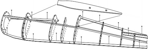
5. When dry remove frame from plan and cement the right side formers to the center keel making sure they are straight across from their counterpart.
6. Cement the other A5 side keel and A6 in place.
7. Cement rear former F10 on the end of the fuselage.
8. Cement the 1/16” sq. stringer that falls on top of F5 into place. Cement F11 - F13 into place to form cockpit area.
9. Six F14 pieces get cemented between F1 and F2. Cement 1/16” sq. stringers into their respective notches down the fuselage.
10 Cement both A7 into place. Then lightly sand fuselage to remove balsa fuzz & excess cement and get it ready for tissue covering.
Wing rib W2 can be cemented at angle IF you
are building a FLYING model. To obtain this
angle use piece WA during building.
IF building a scale static model, cement W2 at 90°.
2. Cement left side formers F1 through F9 (excluding F3 & F5) on the center keel.
3. Cement side keel A5 into the deep notches in the formers, making sure that the formers remain at a right angle to center keel.
4. Cement formers F3 & F5 into place between center keel and side keel. Note: Use wire to ensure the distance between F2 & F3 will snugly fit the landing gear.
5. Cement A6 into place along side keel and pieces F2 through F6.
Note: to obtain uniform tension on
the fuselage, cement the strings
alternately from left to right sides
and top to bottom.
1. Pin to the plan and cement respectively to each other, all center keel parts (A1-A4).
KIT 703
EDGE 540
AUTHENTIC SCALE FLYING AIRCRAFT
20-3/16" WING SPAN
COPYRIGHT 2012 BY PAUL K. GUILLOW, INC.
OPTIONAL - FLYING STABILIZER / HINGED TAIL SURFACES
If you are building a flying model be sure to use the enlarged FLYING STABILIZER “SF” parts and the 115% over scale stabilizer layout to the right. This will give your plane a more stabile flight.
1. Hinges are shows as dashed rectangles on the Stabilizer and Rudder Layouts. These hinges can be made from scrap plastic or out of an aluminum soda can.
2. With a pencil lightly mark the wood where the hinges with connect the parts to one another.
3. With a sharp hobby knife blade lightly score the balsa wood until it cuts through (be sure not to cut to hard and fast or you may break your parts).
4. When the slots are cut insert the hinges as seen on layouts and drawings. Slide parts together.
5. When they are aligned put a dab of glue on either side and let dry.
HINGE OPTION INSTRUCTIONS
Note: follow only if you want your model to have movable tail surfaces.
1. With the landing gear
upside down at about a
45º angle slide it into
fuselage between F2 and
F3 so that wire is above
the F14 pieces.
3. Continue to slide landing gear wire into
fuselage until centered, then down into
place on top of center keel and the
F14 pieces. Cement into place.
2. Rotate the landing gear 180º
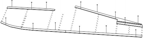
MAIN LANDING GEAR
WIRE PLACEMENT
After bending the wire, cement it to F10 & A2 as shown
in Full Size Side View below. Make sure that the wheel
axle is pointing inward so the wheel will be centered on
your model under the bottom keel.
When adhesive is dry trim
off excess tissue
Paint a bit more glue mixture
through the tissue for good bond.
Lay tissue down and
smooth out any wrinkles
Brush 50% white glue 50% water
mixture on outside edges of frame
No glue applied
on inside pieces
Cut a piece of tissue
a bit oversized for the
frame you are covering.
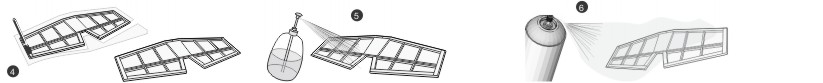
Preparing for covering
A good sanding of your framework and sealing the balsa wood pores will give you a nice SMOOTH surface. This will help give you a good tissue covering.
Lightly mist framework with water
to shrink tissue covering tight
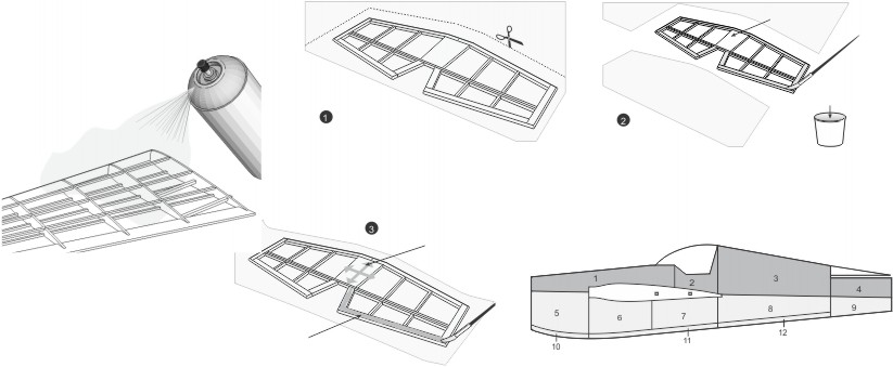
COVERING BALSA FRAMES WITH TISSUE
Give light mist coat of clear acrylic spray paint
Sandpaper all frames to remove any balsa “fuzz” or cement “bumps.” Give the frames a light mist coat of clear acrylic spray paint. When dry, give the frames a final light sanding and another very light spray.
CUT OUT WITH SCISSORS OR MODELERS KNIFE AND FOLD ON DOTTED LINE.
Before cutting out the paper pattern,
use a glue stick to glue red tissue onto
back side so that when you place it on
the model its matches the plane.
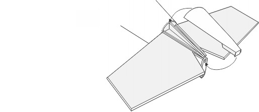
1. Cut out the appropriate tail cover above depending if your building a static or flying Edge 540 model. You can trace this pattern onto some blank paper if you don’t want to cut / ruin your plan.
2. Slide tissue covered stabilizer into tail slot and center on fuselage. Cement in place.
3. Cut two 1/16” sq. stringers and cement onto top of stabilizer as show to right. Shape down rear ends to match A2 center keel.
4. Bend paper tail cover down along dashed lines and place on rear of fuselage. Once shaped and fitting properly cement in place along F8, A2 and stringers.
All the major components are made and your model is now ready for assembly. A brief outline of the assembly process is below but you should also study the plan carefully and use the various illustrations, instructions and photos to aid you in making a great looking finished model. The painting on the front of the box is also good reference during final assembly and painting.
1. At this point your frameworks are already tissue covered. Also your Stabilizer and Tail Cover are in place.
2. Finish your main landing gear by adding plastic wheel pants, wheels and A8 landing gear struts.
3. Cement your tail gear wire in place and add tail wheel.
4. Cement clear plastic canopy onto model.
5. Add rudder, making sure it is on straight up and down.
6. Both wings have 3/32” locating sticks sticking out from W2, slide these wings onto A6 on each side of fuselage. Cement in place.
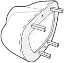
7. Assemble nose cowling using former F0, plastic cowl and four 3/32” sq. locating sticks and then slide cowl onto front of plane.
8. Add water release decals. Decorate plane by adding control surface separations and any other details with a thin black permanent marker.
9. Decide what propeller you want on your model. For flying use the 7” prop, for display you can either use the 4” plastic prop or for more scale appearance carve a 3 bladed prop (material not furnished in kit). Plastic spinner can be used for display model, leave off if flying the plane.
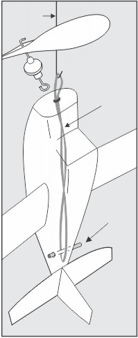
10. Once your propeller assembly is made it’s time to put your rubber motor down into your plane. Tie your ends of rubber thread to make motor loop (instructions below).
11. Make a wire hook out of some scrap wire and then feed the rubber motor down thru the nose cowl all the way to the rear of the fuselage.
12. When rubber motor loop is at back of plane the wood dowel can be slid thru A7’s to hold in place.
13. Using wire hook, pull rubber motor out thru nose and attach to the propeller hook.
14. Seat your propeller assembly down into front of nose cowling.
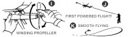
POWERED FLIGHTS
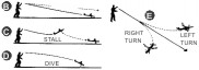
1. Hold model in your left hand with nose facing you. Counting as you turn, wind propeller CLOCKWISE about 50 TURNS (I).
2. Transfer model to right hand and holding it behind wing, raise it head high with propeller tip held in left finger. - do not let it unwind.
The Edge 540 is manufactured in America by Zivko Aeronautics © as a highly aerobatic plane that meets or exceeds the performance of any other aerobatic aircraft available worldwide. Capable of a 420 degree per second roll rate and a 3,700 foot per minute climb rate, it has been flown to victory on the International Unlimited Aerobatics Circuit several times since the 1990s. Widely used at air shows for stunt demonstrations and flown around the world in Air Race World Series, it also proves to be among the best in its class. It pushes the pilot to his physical limits while doing any stunt asked of it, whether it is a simple Immelmann Turn or a Gyroscopic Tumble (which can only be done by 4 aerobatic aircrafts).
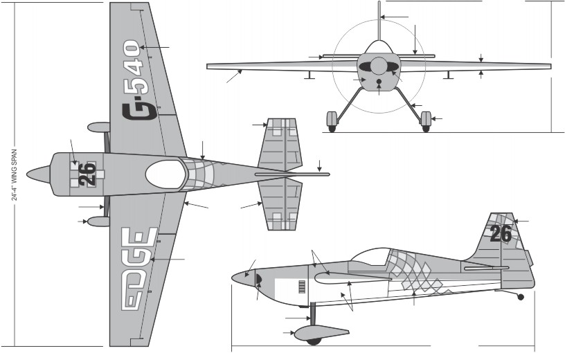
REDUCED 3 VIEW OF COMPLETE MODEL
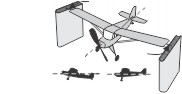
BALANCING / FLYING THE MODEL
TEST GLIDING
IMPORTANT! Never test glide or fly model in windy weather. Wait for a day that is calm or only slightly breezy.
1. If possible choose a grassy area free of trees, wires, etc. such as a field, park or playground.
2. Hold model by fuselage just behind wing (A) . Lift slightly above your head with nose of plane pointed into any breeze.
3. Aim model at an imaginary spot about 50 feet in front of you and then, gently but firmly, thrust it forward on an even line, releasing it at the last moment. DO NOT THROW!
4. If properly balanced, model should glide evenly about one half the distance aimed for and touch down in a smooth landing (B).
BEFORE FLYING CHECK FOR WARPS
The wings and tail surfaces should be checked for possible warps. These can be detected by looking at the surfaces from the center of the model, from the front and the rear. If warps are apparent, steam is the most effective way to remove warps. With the tea kettle bring ½ pot of water to a boil so steam is pouring-out of the spout. Turn down the heat until the water is just at or above the boiling point and the steam slowing moving out of spout. Hold the model in a manner that allows you to twist the warped surface and still keep your hands away from the steam. Move the warped area over the steam in a circular motion until you see the covering relax and loosen. Gently twist the surface in the opposite direction, a little more than is needed to remove the warp. Take the model away from the steam, holding the surface in the same twisted state until the surface tightens up again. After releasing the surface, the warp should be gone. If more twist is needed, repeat the procedure.
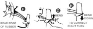
3. Turns or "banks" (E) can be corrected as follows: First hold model in your left hand with TOP of plane towards you (F). To straighten out a LEFT TURN, hold rear edge of rudder in your finger tips and while breathing warm air on the rudder surface, bend UP slightly (G) . Correct a RIGHT TURN the same way EXCEPT bend the rudder edge slightly DOWN(H).
4. After each adjustment, test glide model to see if it glides properly. If not, repeat any correction needed until it glides as described in Step 4 of TEST GLIDING.
BALANCING
Before flight testing, your model MUST be balanced (refer to Wing Layouts on opposite side of plan for POINTS OF BALANCE) The model will require the addition of a small amount of weight at the nose to balance properly. For weight, use the clay included in this kit and press it onto the lower part of the nose cowl.
MODEL IN
BALANCE AFTER
WEIGHT IS ADDED
TAIL HEAVY - ADD
WEIGHT TO NOSE
OF MODEL
CORRECTIONS FOR POOR GLIDE
1. If model climbs & "stalls." its TAIL HEAVY (C) . Correction: Add a small piece of clay to nose.
2. If model dives into ground, it is NOSE HEAVY (D). Correction: Remove some clay from nose or add a small piece of clay to tail.
This model kit is 1/14 scale, or approx
14 times smaller than a real Edge 540.
These drawings show
a plane using included
decals and color scheme
illustrated on the front of
the box.
(Cover frame with pieces of tissue in the suggested order shown below.)
Per color scheme - Red tissue on top and white tissue on bottom.
Note: Do not tissue the area where the wings attach to the fuselage.
Leave the wood clear for best cement bond.
CUTTING OUT
PLASTIC PARTS
Manufacturer/designer: Zivko Aeronautics, Inc. ©
Capacity: one, pilot only.
Dimensions: wing span 24’-4” (7.42m), length 20’-7” (6.27m)
Engines: Lycoming IO-540; 340 h.p. B&C starter and 8 amp alternator, slick mags, Bendix fuel injection system.
Propeller: Hartzell HC-C3YR-1AX1 or HC-C3YR-4AX, composite.
Empty Weight: 1,170 lb (531kg)
Fuel: 19 gal in fuselage, 44 gal in wings. Capacity 238 liters.
Max. take off weight: 1,800 lb (817kg)
Max. speed: 265 mph (230 knots)
Max rate of roll: 420°/sec.
Max. Climb Rate: 3,700 ft/min (1,128 m/min)
G-limits: 10 G.
COVER TOP
with
RED TISSUE
COVER BOTTOM
with
WHITE TISSUE
The Edge 540 is decorated
in many colorful schemes
at air shows. If you don’t
like our colors and decals
do a little research online,
be creative & have some
fun coming up with your
own Edge 540.
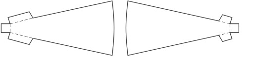
Form four strand double loop out of
the length of rubber thread
Tie the rubber thread in a knot
(as show) to complete rubber
motor. make sure this knot is
towards back by A7 when
placing in your fuselage.
For long flights, more propeller turns are possible if you lubricate the rubber motor BEFORE it is installed in the model. To do this, pick up a bottle of ArmorAll lubricant from your local auto parts store. Put the rubber band in a plastic baggie along with 2 sprays of the lubricant. Rub it into the rubber motor through the bag. Take the rubber band and stretch it a few times and then wipe off excess lubricant. Install motor in model and wind slowly - this will force "lube" into the rubber. While holding the model, let it unwind and repeat.
HINTS ABOUT RUBBER MOTOR
When winding propeller, DO NOT exceed 300 turns. Over winding will cause rubber motor to break and damage model.
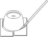
With a modeling knife lightly score the edge of the plastic part. Then flex the excess material up and down to snap it off. Do not try to cut plastic all the way through on the first cut at the risk of slipping and damaging the part. Once cut out, use sandpaper to lightly smooth the cut edges.
3. Facing breeze, if any, launch model in a straight line releasing propeller at the last moment. Do not throw - launch as if test gliding.
4. Model should fly in a fairly straight line with this low power (J). If it does, add 15 more turns for next flight - 75 in all. If not, observe flight pattern and make adjustment needed at described in CORRECTIONS FOR POOR GLIDE.
5. Increase propeller turns for each successful flight up to a maximum of approximately 300 turns. Do not over wind and break motor band.
6. When properly adjusted, model should normally fly in a climbing circular pattern (K) .
7. If model, while under full power (maximum turns) continues to "stall out" (C), cement a thin strip of balsa behind TOP of wood thrust bearing (L). This shim adds DOWN THRUST.
8. For longer flights, stretch rubber motor band about twice original length and then "wind in" propeller turns(M). You'll need a friend to hold model as you hold thrust bearing in your fingers and wind propeller. Do not over wind. Good Luck and Good Flying!
Note: for movable
stabilizer do not glue
along this hinge line.
Rudder shown with
optional hinges and
movable fin surface.
Stabilizer shown with
optional hinges and
movable elevator surfaces.
F0 is cemented into the cowl and fits on the front of the fuselage, using four 3/32” sq. by ½” long sticks for exact placement on the front of the fuselage.
Some pins omitted
for clarity
Some pins omitted
for clarity
See note at
right regarding
wing dihedral