An easy method
to determine strip
stock sizes
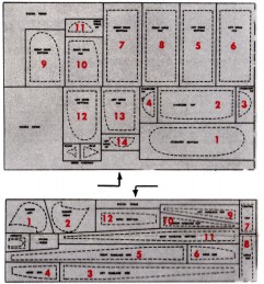
REMEMBER! THESE SOLID BLACK AREAS INDICATE BALSA STRIP SIZES.
KIT 702
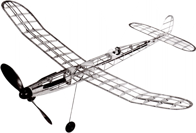
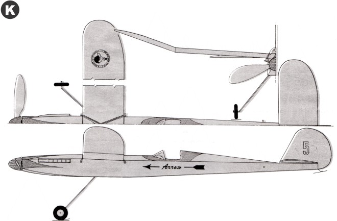
Arrow
28" WING SPAN 27½ Overall Length
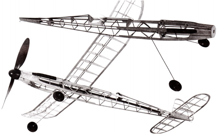
A Stage 2 Junior Contest Endurance Model
GUARANTEED TO FLY IF INSTRUCTIONS ARE FOLLOWED
COPYRIGHT 1967 BY PAUL K. GUILLOW, INC.
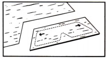
The frames for model are assembled directly over the full size layouts printed on this side of plan. The plan has been divided into easy-to-read work areas and it is suggested that, starting with area "A," you complete the frames in one area before starting the next frame project.
Although the frames are built directly on the layouts the plan MUST first be laid flat on a workboard and covered with wax paper to prevent frames from sticking to it during assembly. For a workboard, use corrugated cardboard, soft wood, Celotex, etc.—any flat surface into which you can easily stick common pins.
The model frames are built from balsa sheet and strip stock. Parts on the sheet stock are die-cut and lettered to correspond with the letters on the plan (CI, C2, C3, etc.). The strips, which are cut to various short lengths as needed, must first be cut to FULL LENGTH from the sheet of strips as illustrated below.
IMPORTANT PRE-WORK INFORMATION
In addition to the contents of this kit, you will need the following tools and accessories: model airplane cement, clear dope, dope thinner, ¼" wide artist brush, model knife and fine sandpaper all of which can be obtained at your local hobby store. Also required and usually found at home are common pins (50), wax paper and a single edge razor blade.
TOOLS AND ACCESSORIES REQUIRED
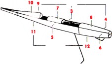
DETAIL OF AIRPLANE FRAME WORK
NOTE: ALL FRAMES COVERED WITH TISSUE BEFORE ASSEMBLY!
Plan and Instruction Sheet
PATENT APPLIED FOR
SPECIAL NOTE!
DO NOT use plastic model cement for building this model.
BUILDING THE STABILIZER AND RUDDER FRAMES
|
The balsa frame pieces are cemented to each other as they are placed on the layouts
Use common pins to fasten pieces in place-locations shown by black dots.
Black letters indicate die-cut parts (all other pieces are cut from balsa strips).
Red numbers indicate order of frame assembly.
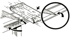
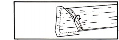
The width and thickness of balsa strips found by matching
|
|
the end with the solid black areas on layouts (see sketch). Cut strips to length as needed.
Be sure to let cement dry HARD before removing frames from layouts then trim ends of balsa strips as indicated on plan.
Working carefully, sandpaper STABILIZER rib ends as shown in sketch to left on plan. (Below on here)
Finally apply second coat of cement to all joints for added strength.
|
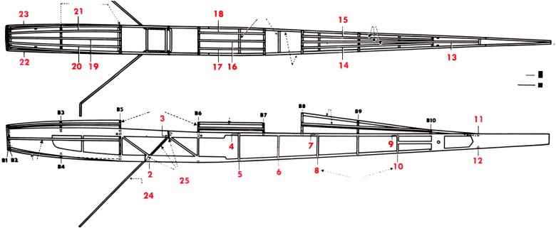
BUILDING THE FUSELAGE (BODY) FRAME - STEP 1
|
Following the small red numbers, assemble the two side frames on the layouts just as you assembled the rudder and stabilizer frames. (Drawing No. 1)
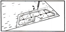
When cement has dried, remove common pins CAREFULLY and then lift the LEFT SIDE frame from its layout.
The RIGHT SIDE frame remains on the layout with all pins removed except two or three thru die-cut parts A1and A2 as you can see in Drawing No. 2
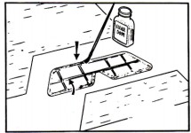
The next job is to join the two frames together at the tail ends and install former B5 in place between the frames.
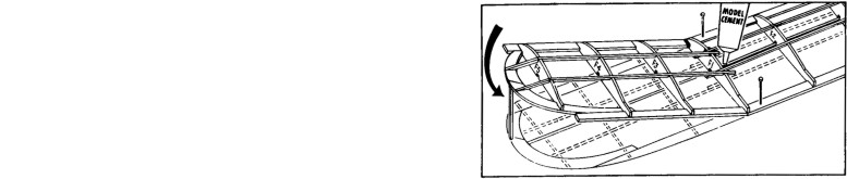
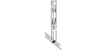
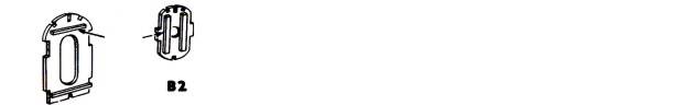
First re-enforce FORMERS B2 and B5 with two balsas sticks as shown in Drawing No. 3. Next line up the LEFT SIDE frame over the RIGHT SIDE frame and then cement and pin the tail ends together as shown in Drawing No. 2. While cement is STILL WET, raise the front of frame and cement former B5 in place between the frames as illustrated. (Drawing 2)
|
|
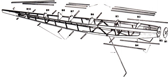
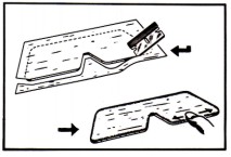
After you are sure the cement holding the fuselage frame together is dry, remove all remaining pins and carefully lift from layout. From this point on, the fuselage frame is completed off the plan.
Now, cement former B2 between the nose ends of side frames, holding together with finger tips or rubber band until dry (22) Drawing No. 4
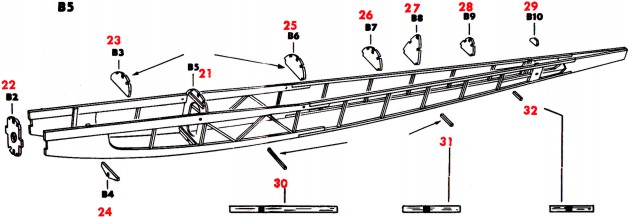
Next cement formers B3 and B4 in place (23-24). Add remaining formers — B6, B7, B8, B9, B10 (25-26-27-28-29).
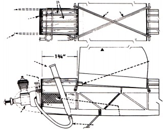
In addition to formers, other pieces are needed to strengthen the fuselage frame. These are called "CROSS MEMBERS" and are cut from balsa strips. Following the red numbers cut and cement cross members in place between side frames. (30-31-32) Actual size of cross members shown immediately below Drawing No. 4.
|
BUILDING THE FUSELAGE (BODY) FRAME - STEP 2
Instead of working on a layout, this second step in assembly is performed while you hold the frame in your hands or while it is setting on the workboard. The location of parts to be added to the fuselage frame are shown on the top and side views and Drawing No. 5 below. As before, follow the red numbers for proper work order.
Cement former B1 to B2 — see Drawing No. 5 below. (1)
Following the red numbers, cut remaining cross members to size and cement between side frames. (2-3-4-5-6-7-8-9-10-11-12)
Top and Bottom strips, called STRINGERS are next added. These are attached to frame longer than needed and then cut to actual length after the cement has dried. (13-14-15-16-17-18-19-20-21-22-23)
Using two pair of pliers, carefully bend the landing gear wire to shape. (refer to full size layout directly below). Cut off any excess length with wire cutters.
Next comes the installation of the wire gear. Slip wire gear between side frames as shown and cement in place. (24) Using household thread, bind gear securely to diagonal strips and side frames. Coat thread binding with cement. (25)
Finally, gives all joints a second coat of cement for added strength.
SPECIAL NOTE: Some of the drawings that follow are NOT illustrations of the actual model you are building. They merely show the general way model parts are covered, doped, assembled, etc.
SANDING AND DOPING THE FRAMES
|
CLEAR DOPE: A special liquid used by model builders for priming balsa wood and as an adhesive for attaching tissue covering to model frames. Also used as
|
|
a protective coating over tissue covered frames when diluted in half with dope thinner. Clear Dope and Dope Thinner available at your hobby dealer.
|
Lightly sandpaper all frames to remove any balsa "fuzz" or cement "bumps." Give outside edges of all frames on coat of clear dope. (Drawing No. 12). When dry, give frames a final light "smooth-up" sanding.
COVERING THE FRAMES WITH TISSUE
Covering model frames with tissue is actually quite easy although often a problem for a beginner. The directions that follow show the five basic steps for covering a model frame and even a "first timer" can enjoy success if these instructions are carefully observed.
1. MARK AND CUT TISSUE OVERSIZE
2. BRUSH CLEAR DOPE ON OUTSIDE EDGES OF FRAME.
NO DOPE APPLIED ON INSIDE PIECES
5. DOPE EDGES - SMOOTH DOWN
FOR OVERLAP EDGES, CUT
TISSUE SO NO TRIM IS NEEDED
The five basic steps in covering are as follows:
1. Trace and cut tissue to size. (Drawing No. 7).
2. Apply coat of Clear Dope to frame. (Drawing No. 8).
3. Immediately set tissue on doped frame BEFORE it has a chance to dry and smooth flat with finger tips. (Drawing No. 9).
4. Trim off overhang with razor blade. (Drawing No. 10). Sandpaper can be used if blade no available.
5. Apply coat of Clear Dope to trimmed edges and smooth down any loose tissue with finger tips. (Drawing No. 11). Where a piece of tissue of tissue
overlaps another it is best to cut the overlapping edge so that no trim is needed. (Drawing No. 12).
The Tissue Pattern Key shows how tissue should be marked with soft pencil (solid lines) to get enough pieces to cover all parts. No need to trace actual frame outlines (dotted lines). Cut the square sections apart and dope to frames as needed following red numbers for best work order. Trim off "overhang" when dry.
Before assembling model, spray all surfaces of tissue covered parts with clean water. As water dries, it will shrink tissue smoothly on frames. Use an atomizer (Drawing No. 13) or facial tissue dipped in water. Apply moister lightly and sparingly to avoid breakage of tissue.
When dry, give all surfaces of the tissue covered parts ONE coat of Clear Dope that has first been thinned in half Dope Thinner, DO NOT use full strength as it comes in bottle. (Drawing No. 14).
Finally cement plastic nose cowl to fuselage — refer to drawing No. 5.
SPRAYING TISSUE WITH CLEAR WATER
IMPORTANT!
MIXTURE OF HALF DOPE AND HALF DOPE THINNER
|
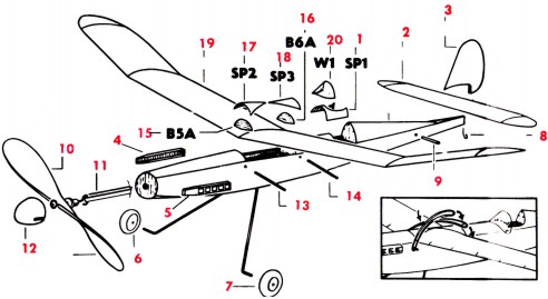
The model is now ready for assembly — see Drawing No. 15 below. Before Assembly, be sure to scrape tissue away in spots on stabilizer center rid before attaching rudder so that wood will bond to wood.
Cut windshield W1 from celluloid using pattern furnished below. Next trace the stiff paper parts SP-1, SP-2, and SP-3 on white paper and cut to shape. (Material not furnished in kit — use any white writing paper you may have at home).
Carefully cut the spinner and exhaust stacks from plastic sheet. Sandpaper the cut edges smooth then set part aside.
Prepare tail skid using a common pin.
|
|
Now referring to Drawing No. 15, assemble model in order shown be the red numbers.
Cement stiff paper cockpit pattern SP-1 to fuselage.
Next, cement wing formers B5A and B6A to the top of leading and trailing edges of the wing. add stiff paper fillets SP-2 and SP-3.
At this time, cover stiff paper pieces SP-1, SP-2 and SP-3 with tissue that matches covering of wing and fuselage.
Proceed with rest of model assembly noting that details of the propeller unit assembly and rubber motor installation are illustrated in Step 1 that follows
|
INSTALLING RUBBER POWER UNIT
|
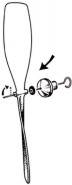
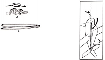
Assemble propeller unit and tie ends of rubber thread in kit to form a motor band. (Drawing No. 16).
|
|
Install one end of motor band in fuselage (Drawing No. 17) then fasten other end to wire propeller shaft.
|
TYING RUBBER THREAD (MOTOR)
HINTS ABOUT RUBBER MOTOR
When winding propeller, DO NOT exceed 300 turns. Over winding will cause rubber motor to break and damage model.
For long flights, more propeller turns are possible if you lubricate the rubber motor BEFORE it is installed in model. To do this, obtain a mixture of one part liquid green soap and two parts glycerin from your druggist. Place a few drops of this mixture in your hands and rub it into the rubber motor. Stretch rubber a few times and wipe off excess lubricant. Install motor in model and wind slowly - the will force "lube" into rubber.
In case rubber motor breaks, replace it with T-56 rubber thread available at your local hobby shop. Length needed - 96 inches.
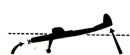
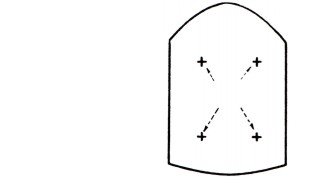
NOSE HEAVY - ADD WEIGHT HERE
MODEL IN BALANCE AFTER WEIGHT IS ADDED
Before flight testing your model, be sure and "balance" it as shown in Drawing No.18. This model has been designed to require little if any weight when built as per these instructions. However, if weight is needed to properly balance model, add a small amount of modeling clay, window putty or similar pliable material to tail if model is nose heavy. Drawing No. 19. (Cut small hole in tissue and force weight between side frames where they join at tail).
If tail heavy add needed weight to the nose of model to bring into balance. This weight can be spread on lower area of fuselage adjacent to formers B1 and B2.
Building and flying your own balsa model airplane can be one of the most interesting and enjoyable hobbies providing you spend the time necessary to do a good job. This Guillow model is especially designed for ease of assembly and good flight performance and you can enjoy both IF you follow the special Build-by-Number instructions that have been developed by Guillow
|
|
model engineers as an aid to a new model builder. Experienced model builders will find this "Junior Contest" model simple to build and a joy to fly. You too can have the same success if you work SLOWLY and CAREFULLY making sure that each separate job is complete before attempting the following step.
Good luck and good flying!
|
ACTUAL SIZE OF CROSS MEMBERS
THE FUSELAGE (OR BODY) FRAME IS BUILT PARTLY ON THIS PLAN AND THEN COMPLETED AFTER REMOVAL FROM LAYOUTS. STEP 1 OF BUILDING THE FUSELAGE COVERS THE ASSEMBLY OF THE RIGHT AND LEFT SIDE
|
|
FRAMES AND THE INSTALLATION OF THE LINE-UP FORMER.
THE FINAL ASSEMBLY OF THE FUSELAGE FRAME IS GIVEN IN STEP 2 ON THE OPPOSITE SIDE OF THIS PLAN.
|
JUST FOLLOW THE RED NUMBERS FOR BUILDING EACH FRAME AND YOU'LL AVOID ASSEMBLY ERRORS.
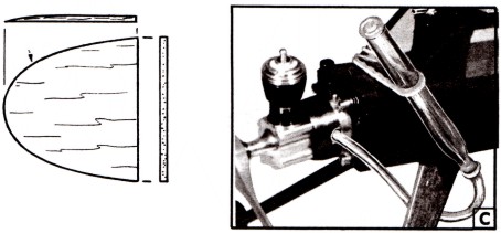
SPORT FLYING. Modify fuselage, add firewall and mount a standard Cox .020 PEE-WEE engine (A). Be sure "pop-up" tail group is installed (B) to prevent loss of model. Mount prop BACKWARDS. Fuel: ½ to ¾" eyedropper full.
CONTEST FLYING. Modify .020 PEE-WEE and substitute eyedropper for regular tank. (A and C). Fuel: 15 seconds motor run or less.
(SOME PINS OMITTED FOR CLARITY)
(SOME PINS REMOVED FOR CLARITY)
CEMENT TAIL ENDS TOGETHER
TOP CENTER STRINGERS ARE 1/16" X 3/32"
ALL OTHER STRINGERS ARE 1/16" SQ.
COVER SP1, SP2 AND SP3 WITH TISSUE AFTER ATTACHMENT TO FUSELAGE AND WING
FORM FOUR STRAND DOUBLE LOOP WHEN INSTALLING RUBBER MOTOR IN FUSELAGE
SHADED AREAS INDICATE SUGGESTED TRIM COLOR
— DARK TISSUE OVER LIGHT COVERING
OPTIONAL - GAS ENGINE CONVERSION - FOR EXPERIENCED
MODELER ONLY
FULL SIZE FIREWALL
—1/16" PLYWOOD
MOUNTING MOTOR AND FUEL TANK
PROP SIZE 3" PITCH—5½" DIA.
3 WASHERS — BOTH TOP BOLTS
MODIFIED COX .020 PEE WEE
WATER SPRAYING AND DOPE COVERED PARTS
SANDING RIB EDGES FLUSH WITH REAR OF TRAILING EDGE
|
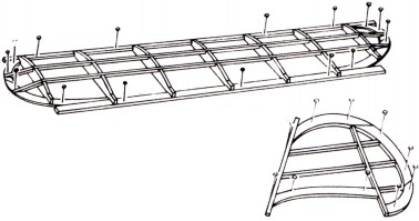
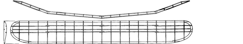
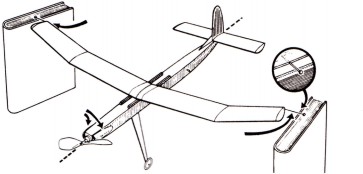
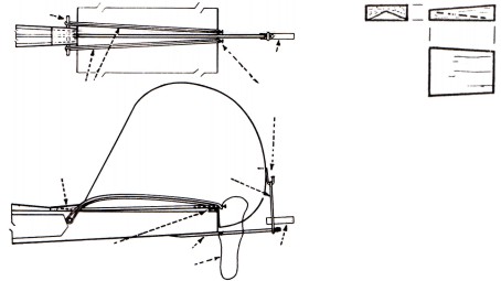
instead of being flat frame like the stabilizer, the wing of this model is built with its four panels at different angles to each other as shown in the reduced size plan at right. (Drawing No. 1)
The building of this "angled" frame (known as polyhedral wing) is quite simple providing you follow the exact assembly sequence shown be the red numbers.
First build the entire wing frame flat on the Wing Layout following red numbers 1 thru 50 and, VERY IMPORTANT, making sure that NONE of the parts are cemented together where the wing panels join - see notes on Wing Layout. These parts MUST remain uncemented so they can move freely when doing steps 48, 49and 50. Also, the bottom spar parts (13, 14, 15, and 16) are REMOVED from layout immediately after being cut and fit in place. Do not cement to wing frame until later.
After completing step 47, remove all pins from Right and Left Wing Tip Panels and raise them as shown in Drawing No.2 using balsa strip under each wing tip to set the correct height. Now cement the parts together where these panels
|
|
join the
center panels (48 and 49)
When cement has hardened, remove pins from Right Center Panel and raise as shown in Drawing No. 3 again using balsa strip for setting height. Cement all parts together where Right and Left Center Panels join (50).
Remove remaining pins and lift wing frame from layout.
Now cement the pre-cut bottom spar pieces yo the wing ribs and tips. This completes the assembly of your "Polyhedral" wing frame.
Trim ends of balsa strips as indicated on Wing Layout.
Work carefully, sandpaper wing rib ends as shown in Drawing No. 4 at left.
Finally, apply a second coat of cement to all joints for added strength.
|
USE BALSA STRIP TO SET HEIGHT OF WING PANEL
DETAIL OF WING CONSTRUCTION
(COCKPIT AREA COVERED IN STEP "H"
MODEL SHOWN NO. 603 JAVELIN
BALSA SIDE COWLS
—OPTIONAL
TYPICAL EYE DROPPER FUEL TANK INSTALLATION
ENGINE THRUST SETTING. Mount engine with washers between motor and firewall (A). Use bolts and nuts, not screws, for engine mounting.
LIMIT POP-UP TAIL GROUP 40° TO 45° —NOT OVER. THIS IS DETERMINED BY LENGTH OF THREAD.
BALSA SHEETING ALL AROUND NOSE OF FUSELAGE
1/16" X ¼" X 2" STRIP UNDER WING L.E.
1/16" X 3/16" X 1" STRIP UNDER WING T.E.