An easy method
to determine strip
stock sizes
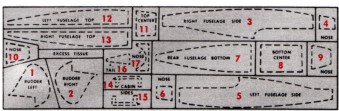
REMEMBER! THESE SOLID BLACK AREAS INDICATE BALSA STRIP SIZES.
KIT 701
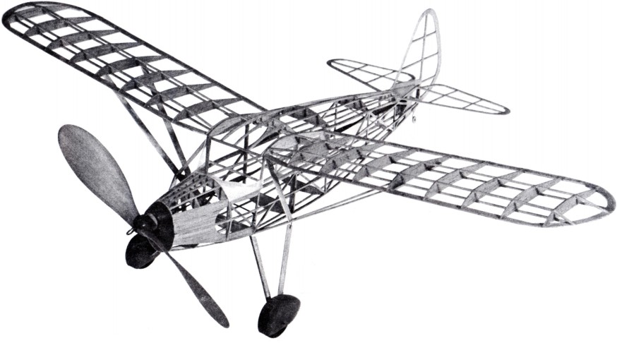
FAIRCHILD F-24
25" WING SPAN 17½" Overall Length
A Stage 2 Junior Contest Endurance Model
GUARANTEED TO FLY IF INSTRUCTIONS ARE FOLLOWED
COPYRIGHT 1967 BY PAUL K. GUILLOW, INC.
The frames for model are assembled directly over the full size layouts printed on this side of plan. The plan has been divided into easy-to-read work areas and it is suggested that, starting with area "A," you complete the frames in one area before starting the next frame project.
Although the frames are built directly on the layouts the plan MUST first be laid flat on a workboard and covered with wax paper to prevent frames from sticking to it during assembly. For a workboard, use corrugated cardboard, soft wood, Celotex, etc.—any flat surface into which you can easily stick common pins.
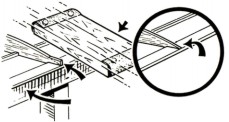
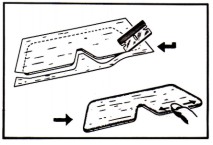
The model frames are built from balsa sheet and strip stock. Parts on the sheet stock are die-cut and lettered to correspond with the letters on the plan (CI, C2, C3, etc.). The strips, which are cut to various short lengths as needed, must first be cut to FULL LENGTH from the sheet of strips as illustrated below.
IMPORTANT PRE-WORK INFORMATION
In addition to the contents of this kit, you will need the following tools and accessories: model airplane cement, clear dope, dope thinner, ¼" wide artist brush, model knife and fine sandpaper all of which can be obtained at your local hobby store. Also required and usually found at home are common pins (50), wax paper and a single edge razor blade.
TOOLS AND ACCESSORIES REQUIRED
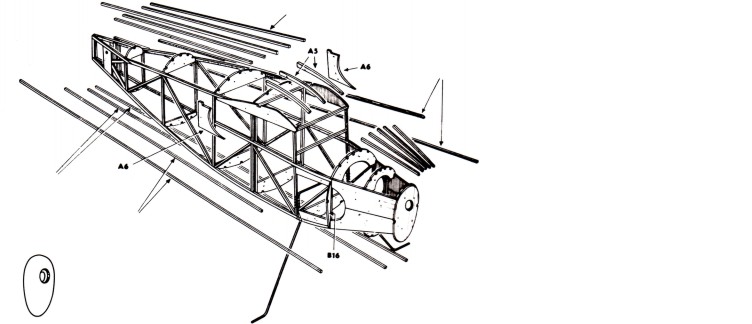
DETAIL OF AIRPLANE FRAME WORK
NOTE: ALL FRAMES COVERED WITH TISSUE BEFORE ASSEMBLY!
Plan and Instruction Sheet
PATENT APPLIED FOR
SPECIAL NOTE!
DO NOT use plastic model cement for building this model.
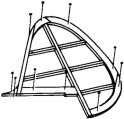
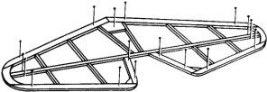
BUILDING WING STRUTS, STABILIZER AND RUDDER FRAMES
|
The balsa frame pieces are cemented to each other as they are placed on the layouts
Use common pins to fasten pieces in place-locations shown by black dots.
Black letters indicate die-cut parts (all other pieces are cut from balsa strips).
Red numbers indicate order of frame assembly.
The width and thickness of balsa strips found by matching
|
|
the end with the solid black areas on layouts (see sketch). Cut strips to length as needed.
Be sure to let cement dry HARD before removing frames from layouts then trim ends of balsa strips as indicated on plan.
Finally apply second coat of cement to all joints for added strength.
|
The two wing frames are built in much the same way as the stabilizer and rudder frames with various parts being cemented together and pinned in place in the order shown by the small red numbers.
Since both the right and left wing frames are quite similar, you can build either one first.
Be sure to let cement dry HARD before removing frames from the layouts.
Working carefully, sandpaper wing rib ends as shown in sketch at left.
Finally, apply a second coat of cement to all joints for added strength.
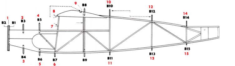
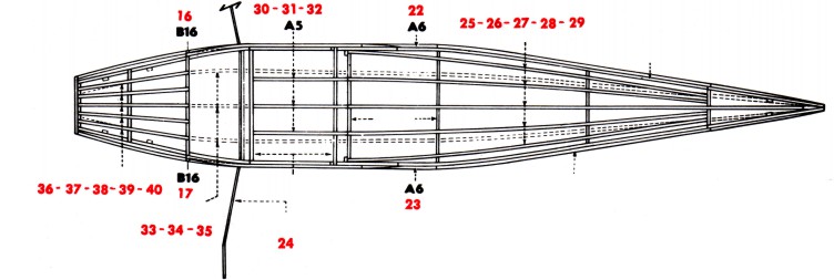
BUILDING THE FUSELAGE (BODY) FRAME - STEP 1
|
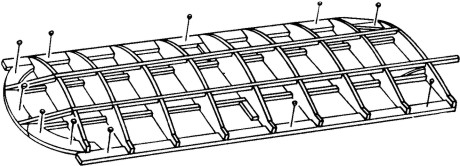
Following the small red numbers, assemble the two side frames on the layouts just as you assembled the rudder and stabilizer frames. (Drawing No. 1)
When cement has dried, remove common pins CAREFULLY
|
|
and then lift the LEFT SIDE frame from its layout.
The RIGHT SIDE frame remains on the layout with all pins removed except two or three thru die-cut parts A1and A2 as you can see in Drawing No. 2
|
|
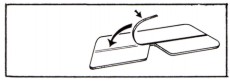
The next step is to join the two frames together at the tail ends and install a LINE-UP FORMER in place between the frames.
First build the line-up former as shown at left using the die-cut balsa formers B8 and B9 and strip stock. When cement has dried hard, remove line-up former from plan.
Next lay the Left Side frame over the Right Side frame and then cement and pin tail ends together as shown in Drawing No. 2. While the cement is STILL WET, raise the nose end of the Left Side frame and cement the line-up former in place between the
|
|
frames as illustrated.
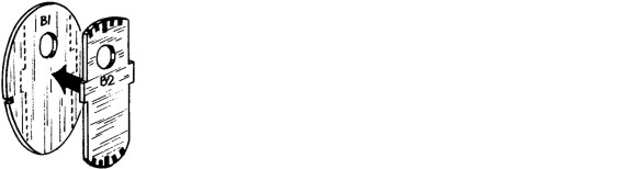
While frames are drying, cement formers B1 and B2 together as shown in Drawing No. 3.
After you are sure the cement holding the fuselage frame together is dry, remove all remaining pins and carefully lift from layout. From this point on, the fuselage frame is completed off the plan and the next assembly steps are given on the opposite side of this plan sheet.
|
BUILDING THE FUSELAGE (BODY) FRAME - STEP 2
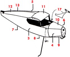
Instead of working on a layout, this second step in assembly is performed while you hold the frame in your hands or while it is setting on the workboard. The location of parts to be added to the fuselage frame are shown on the top and side views and Drawing No. 4 below. As before, follow the red numbers for proper work order.
Referring to Stage One above, cement double former B1/B2 between the nose of the Side Frames holding together until dry. Next add the rest of the formers and cross members according to rotation shown by the red numbers.
using two pairs of pliers, carefully bend the landing gear wire to shape. (Refer to full size drawing directly below). Cut off any excess length with wire cutters.
Refer to Stage Two for succeeding operations. Cement formers B16to side frames then add top, bottom and side stringers. Next install the wire landing gear binding it with thread to balsa strips. Coat binding with cement.
Cement die-cut pieces A5 and A6in place. Finally give all joints a second coat of cement for added strength.
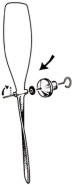
At this time the plastic nose cowl should be trimmed to shape and then "dry fitted" over former B2. (Drawing No. 5)
A slight amount of light sanding will be necessary to obtain a perfect fit. CAUTION! Do not sand B2 too much resulting in a loose fit. Set cowl aside until after fuselage frame is covered with tissue.
SPECIAL NOTE: Some of the drawings that follow are NOT illustrations of the actual model you are building. They merely show the general way model parts are covered, doped, assembled, etc.
SANDING AND DOPING THE FRAMES
|
CLEAR DOPE: A special liquid used by model builders for priming balsa wood and as an adhesive for attaching tissue covering to model frames. Also used as
|
|
a protective coating over tissue covered frames when diluted in half with dope thinner. Clear Dope and Dope Thinner available at your hobby dealer.
|
Lightly sandpaper all frames to remove any balsa "fuzz" or cement "bumps." Give outside edges of all frames on coat of clear dope. (Drawing No. 12). When dry, give frames a final light "smooth-up" sanding.
COVERING THE FRAMES WITH TISSUE
Covering model frames with tissue is actually quite easy although often a problem for a beginner. The directions that follow show the five basic steps for covering a model frame and even a "first timer" can enjoy success if these instructions are carefully observed.
1. MARK AND CUT TISSUE OVERSIZE
2. BRUSH CLEAR DOPE ON OUTSIDE EDGES OF FRAME.
NO DOPE APPLIED ON INSIDE PIECES
5. DOPE EDGES - SMOOTH DOWN
FOR OVERLAP EDGES, CUT
TISSUE SO NO TRIM IS NEEDED
The five basic steps in covering are as follows:
1. Trace and cut tissue to size. (Drawing No. 7).
2. Apply coat of Clear Dope to frame. (Drawing No. 8).
3. Immediately set tissue on doped frame BEFORE it has a chance to dry and smooth flat with finger tips. (Drawing No. 9).
4. Trim off overhang with razor blade. (Drawing No. 10). Sandpaper can be used if blade no available.
5. Apply coat of Clear Dope to trimmed edges and smooth down any loose tissue with finger tips. (Drawing No. 11). Where a piece of tissue of tissue
overlaps another it is best to cut the overlapping edge so that no trim is needed. (Drawing No. 12).
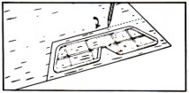
Trace stiff paper pattern SP-1 on white bond writing paper (not furnished in kit) and cut to shape. Cement SP-1 in position on fuselage frame.
The Tissue Pattern Key shows how tissue should be marked with soft pencil (solid lines) to get enough pieces to cover all parts. No need to trace actual frame outlines (dotted lines). Cut the square sections apart and dope to frames as needed following red numbers for best work order. Trim off "overhang" when dry.
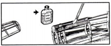
Before assembling model, spray all surfaces of tissue covered parts with clean water. As water dries, it will shrink tissue smoothly on frames. Use an atomizer (Drawing No. 13) or facial tissue dipped in water. Apply moister lightly and sparingly to avoid breakage of tissue.
When dry, give all surfaces of the tissue covered parts ONE coat of Clear Dope that has first been thinned in half Dope Thinner, DO NOT use full strength as it comes in bottle. (Drawing No. 14).
Finally cement plastic nose cowl to fuselage — refer to drawing No. 5.
SPRAYING TISSUE WITH CLEAR WATER
IMPORTANT!
MIXTURE OF HALF DOPE AND HALF DOPE THINNER
|
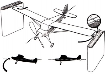
The model is now ready for assembly — see Drawing No. 15 below. Before Assembly, be sure to scrape tissue in spots on any area that prevents wood from binding to wood. Use point of a razor blade or knife.
Following the red numbers, attach stabilizer, stiff paper tail cone, rudder and tail wheel unit. (Cover tail cone with tissue before attaching rubber). Trace windshield (W3) and right and left window area patterns (W1 and W2) on tracing tissue and transfer
|
|
to celluloid sheet. Cut patterns to shape. Cement window areas W1 and W2 in place.
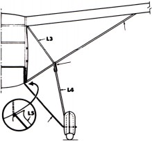
Next cut windshield struts and cement in position—add windshield W3.
Continue model assembly in rotation shown be red numbers. Note that propeller unit assembly and rubber motor installation are shown in Step 1.
|
INSTALLING RUBBER POWER UNIT
DECORATING MODEL - BALANCING MODEL
|
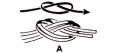
Assemble propeller unit and tie ends of rubber thread in kit to form a motor band. (Drawing No. 16).
|
|
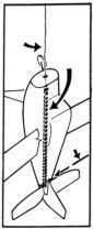
Install one end of motor band in fuselage (Drawing No. 17) then fasten other end to wire propeller shaft.
|
HINTS ABOUT RUBBER MOTOR
When winding propeller, DO NOT exceed 250 turns. Over winding will cause rubber motor to break and damage model.
For long flights, more propeller turns are possible if you lubricate the rubber motor BEFORE it is installed in model. To do this, obtain a mixture of one part liquid green soap and two parts glycerin from your druggist. Place a few drops of this mixture in your hands and rub it into the rubber motor. Stretch rubber a few times and wipe off excess lubricant. Install motor in model and wind slowly - the will force "lube" into rubber.
In case rubber motor breaks, replace it with T-56 rubber thread available at your local hobby shop. Length needed - 48 inches.
TAIL HEAVY - ADD WEIGHT TO NOSE OF MODEL
MODEL IN BALANCE AFTER WEIGHT IS ADDED
Black lines representing control surface separations can be made from the border lines of this plan. (Drawing No. 18). Refer to small three view drawings for location of control lines and any decorations required.
Before flight testing, your model MUST be balanced as shown in Drawing No. 19. (Refer to Wing Layouts on opposite side of plan for POINTS OF BALANCE). The model will require the addition of a small amount of weight at nose to balance properly. For weight, use clay, window putty or any pliable material that you can press onto the lower part of the nose cowl.
Building and flying your own balsa model airplane can be one of the most interesting and enjoyable hobbies providing you spend the time necessary to do a good job. This Guillow model is especially designed for ease of assembly and good flight performance and you can enjoy both IF you follow the special Build-by-Number instructions that have been developed by Guillow
|
|
model engineers as an aid to a new model builder. Experienced model builders will find this "Junior Contest" model simple to build and a joy to fly. You too can have the same success if you work SLOWLY and CAREFULLY making sure that each separate job is complete before attempting the following step.
Good luck and good flying!
|
ACTUAL SIZE OF CROSS MEMBERS
THE FUSELAGE (OR BODY) FRAME IS BUILT PARTLY ON THIS PLAN AND THEN COMPLETED AFTER REMOVAL FROM LAYOUTS. STEP 1 OF BUILDING THE FUSELAGE COVERS THE ASSEMBLY OF THE RIGHT AND LEFT SIDE
|
|
FRAMES AND THE INSTALLATION OF THE LINE-UP FORMER. THE FINAL ASSEMBLY OF THE FUSELAGE FRAME IS GIVEN IN STEP 2 ON THE OPPOSITE SIDE OF THIS PLAN.
|
JUST FOLLOW THE RED NUMBERS FOR BUILDING EACH FRAME AND YOU'LL AVOID ASSEMBLY ERRORS.
Modify nose of fuselage frame to receive motor. Sand plywood firewall smooth then drill the holes for the four engine bolts. mount motor to firewall (note washers used with tip bolts) then cement firewall to formers B3 and B4 after making clearance in B3 for bolts.
For propeller, use one with a 3" pitch and 5½" diameter—available at your Hobby Dealer.
Balance model as shown on plan using clay for nose weight. Test model for straight forward glide—adjust with up or down elevator as needed. Adjust rudder for about a 200 foot left circle.
Initial flights should be made with very short motor runs and preferably in a large grassy area
(SOME PINS OMITTED FOR CLARITY)
REDUCED SIZE RIGHT WING PLAN
(SOME PINS REMOVED FOR CLARITY)
CEMENT TAIL ENDS TOGETHER
DO NOT CEMENT THIS END OF CENTER STRINGER IN PLACE UNTIL AFTER STABILIZER ATTACHMENT. (STEP H). TRIM TO FIT.
TOP AND BOTTOM CENTER STRINGERS ARE 1/16" X 3/32"
DETAIL OF STRUT AND GEAR ASSEMBLY
USE COMMON PINS FOR MAKING "J" HOOKS AND TAIL GEAR
FULL SIZE "J" HOOK—2 REQ.
The ends of rubber thread included in this kit must be tied together as shown (A). form four strand double loop when installing rubber motor in fuselage (B). End knot should be at rear motor mount.
NUMERALS — TOP OF RIGHT WING AND BOTTOM OF LEFT WING. ALSO ON BOTH SIDES OF RUDDER.
OPTIONAL - GAS ENGINE CONVERSION - FOR EXPERIENCED MODLER ONLY
BOLT HOLES FOR COX .020 PEE WEE
FULL SIZE FIREWALL
—1/16" PLYWOOD
AFTER COMPLETION OF FUSELAGE, REMOVE THIS AREA OF FORMER B1/B2 FOR MOTOR CLEARANCE.
PROP SIZE 3" PITCH—5½" DIA.
3 WASHERS BETWEEN ENGINE AND FIREWALL - TOP BOLTS ONLY. NO WASHERS ON BOTTOM BOLTS.
CUT COWL TO FIT AROUND ENGINE
WATER SPRAYING AND DOPE COVERED PARTS