|
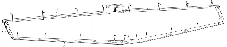
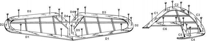
1. Pin to plan and cement respectively to each other all of the “D” stabilizer — elevator parts. Cut to size and cement 1/16" x 3/32" spars and cross members into place.
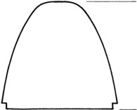
2. Build the fin-rudder frame in similar manner using “C”parts
|
and 1/16" x 3/32" members.
3. When dry remove the frames from plan and round all edges. Sand lightly to remove fuzz and excess cement.
|
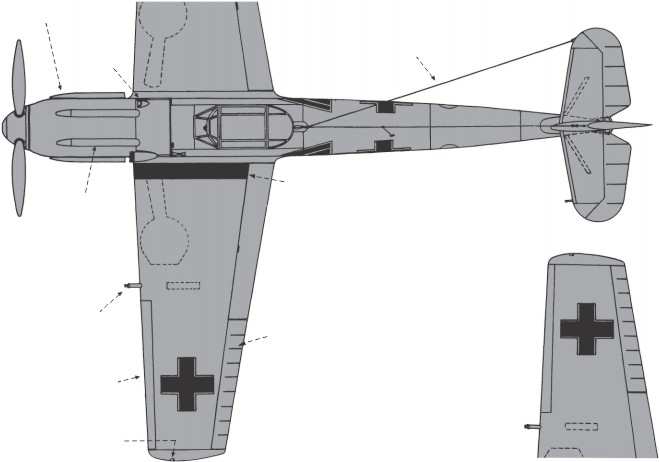
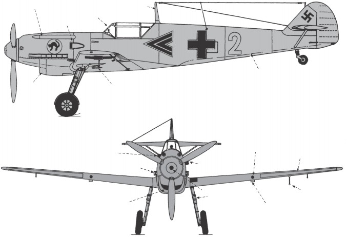
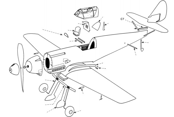
OPTIONAL COLOR SCHEME: ENTIRE UPPER SURFACE IS DULL DARK GREEN. ENTIRE LOWER SURFACE (BELOW COLOR LINE AND BOTTOM SURFACE OF HORIZONTAL STABILIZER) IS FLAT PALE GREEN. SPINNER IS EITHER RED, WHITE OR ANY DISTINCTIVE SOLID COLOR. PROPELLER BLADES ARE FLAT BLACK.
|
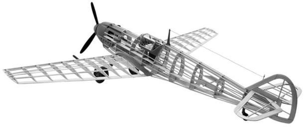
The Messerschmitt Bf109 was a standard German Luftwaffe single seat fighter for nearly a decade. It is believed that more than 33,000 of these fighters were produced between 1936 and the end of World War II. During the war, the Bf109 fought on every front in which the Luftwaffe was engaged and ranks second only to the Supermarine Spitfire as the outstanding fighter of the era. The Bf109 first saw actual combat during the Spanish Civil War where it proved an effective weapon against the Russian fighters of the Republic forces. The Bf109 was
|
considered an excellent fighter since it handled well and possessed excellent low speed control response. It lacked the maneuverability of the Spitfire, but was superior in climb rate and ceiling. In speed, the Spitfire enjoyed a slight margin but the German fighter was definitely better above 20,000 ft. The Bf109s were produced in quantity right up to the end of the war in 1945.
|
|
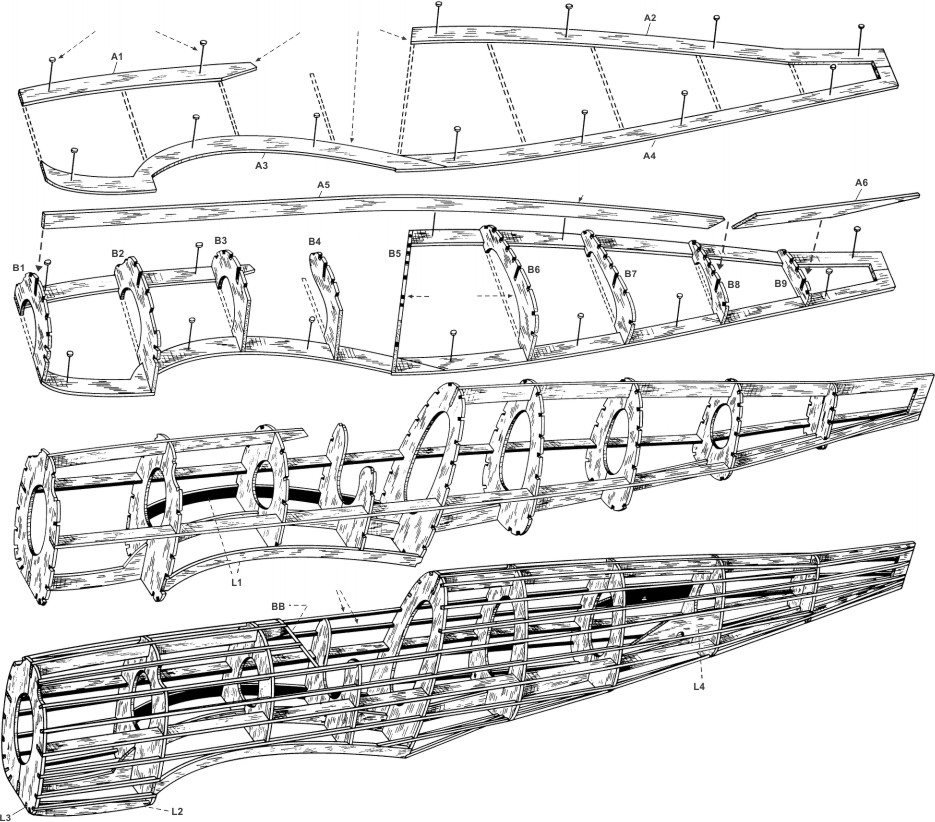
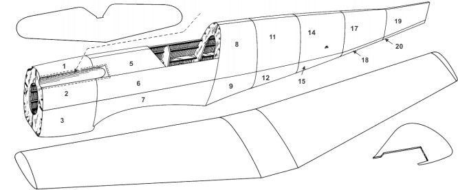
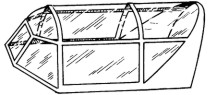
1. Pin the top and bottom keel parts "A1" and "A2" to plan. Cement "A3" and "A4" together and pin to plan.
2. Cement one each of formers "B" into position on keels—be sure formers are at right angles to the keels "A." Cement side keels "A5" and "A6" into deep notches of formers "B." "Note that on some models the side keel "A6" rises upward slightly to blend with the rear of the fuselage."
3. When dry, remove the frame from plan. Cement the opposite halves of formers "B" to center keels and to formers "B" already in position. Cement opposite side keels "A5" and "A6" into position. Cement former "BB" into place as shown.
|
(P-51 Mustang—add former "BA.")
4. Cement the 1/16" square stringers into their respective notches, "Refer to side view of model and fuselage perspective as an aid to stringer locations." To obtain uniform tension on fuselage during this stage of construction, cement the stringers alternately to the left and right sides. If certain stringers show too much tension, soak the stringer or stringers in warm water a few minutes to "limber up" the fibers and they will follow "bold bends" with ease. Note that some stringers are set into place after the "L" parts are cemented in position.
Cement all "L" parts into place. On some models part "L1"
|
bends around the fuselage towards the bottom. Before cementing "L1" into position, soak in warm water as mentioned above to relieve tension. Note: Balsa can be cemented when it is still damp with water. Cement plywood tail wheel into place.
5. Lightly sand fuselage to remove any balsa fuzz and excess cement. If this model has plastic gun troughs, the plastic troughs should be trimmed and cemented into place now before doping and covering the fuselage frame. Refer to special instructions on "Plastic Parts Preparation."
|
|
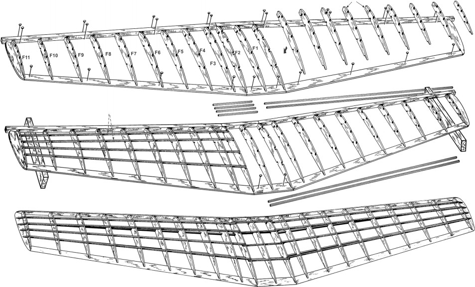
1. Pin to plan and cement respectively to each other, all "E" parts of left and right wing halves, If model has built up leading edge, cement parts "K" together as shown, to form leading edge and pin to plan. If model has 1/4" square leading edges, pin 1/4" squares into position on wing plan. Fit and pin either the built up or 1/4" square center (section leading edge and trailing edge to plan. Do not cement these parts at the dihedral joints at this time.
2. Cement all ribs "F" into position between
leading and trailing edges.
3. When dry, raise tips the required amount as noted on front view of wing and cement the center section
|
leading and trailing edges to the left and right wing leading and trailing edges. While wing is in this position, cement all the top 1/16" square multiple spars into position on left and right wing. Cement center section multiple spars into place. Note how the 1/16" square center section spars are "lap jointed" to the 1/16" square wing spars to form a very strong and quick dihedral joint. Also fit and cement 1/16" square stock to shape the tips.
4. When thoroughly dry, remove wing from plan and cement the bottom 1/16" square wing and center section multiple spars into place, also using the lap joint. With a razor blade or modelers knife, shape the leading edge to blend with the
|
ribs as shown on the typical rib section drawing. Blend the leading edge into the tips and round the tips and trailing edges.
5. Lightly sand the wing to remove any balsa fuzz and excess cement. Prepare the landing gear assembly as shown on the work sheet. The plywood gear assembly can either be cemented into position in the rib slots now or it can be cemented into place after the wing is covered and doped by removing slits of tissue at the slots and cementing gear assembly into place.
|
|
Before starting construction of your model, study the plan and construction procedure carefully so that you will have a complete understanding of the step-by-step method of building this airplane. Guillow engineering has provided you with the most up-to-date method for building a real scale flying model. Only careful attention to detail will insure the success of your efforts. Most prize winning models are the result of patience and careful workmanship. You too, can achieve success by following the example of champion model builders—by working SLOWLY and CAREFULLY at all times. If you plan to build this model
|
as a rubber powered flyer, simply follow the instructions shown on both sides of this direction sheet. For converting to U-Control or R/C, see the special instructions on each shown on the front of the plan. In both cases, the basic model construction is similar to the rubber powered version, but the special construction details required for U-Control and R/C must be made during assembly as per the specific instructions given on the plans.
|
|
After all the frames have been sanded smooth, they must be "pre-doped" so that when you apply the tissue covering, the dope used to adhere the tissue to the frames will not be soaked up by the wood. This makes it much easier and faster to cover the model.
Because of the stringer and former construction use a narrow ¼" or ½" wide brush to dope with. Use dope thinned out 50% with thinner to about the consistency of milk so it will brush easy and dry fast.
The outside surface of all stringers, formers, ribs, leading edges, trailing edges, spars and tips should be given at least three coats of clear dope at which time you will note that the doped surfaces will begin to shine a little. This shows that you have sufficient build up of dope on the wood. Lightly sand wood between coats of dope.
There are two methods of covering a model with tissue. One is to cover with the tissue dry and the other is to cover with the tissue wet. When covering with dry tissue smaller areas are covered at one time. Any area that is covered dry should be tried first to make sure it will not bunch up or wrinkle excessively before doping in place. The covering scheme shown on each plan is suggestive of dry covering. For dry covering, cut the tissue slightly larger than the area to be covered and after doping in place, trim excess tissue with a single edge razor blade.
Dry Covering the Frames
Fuselage: Cover the fuselage in sections as shown on scheme, starting from the front or former Bl and covering vertically between formers. The grain of the tissue should run lengthwise with the fuselage. (The grain of the tissue runs with the width of the tissue sheet as you receive it in the kit).
Wing: On straight tapered wings, you can cover the complete top and bottom of each wing panel between the dihedral break and the last tip rib with one piece of tissue. Use separate piece of tissue for top and bottom of the center section and the tips. Elliptical wings like the Spitfire must be covered with separate pieces of tissue between each rib and from leading edge to the trailing edge. The grain of the tissue must always run span-wise on the wing.
Tail surfaces: The top and bottom of each tail surface can be
|
covered with one piece of tissue. The tissue grain should run spanwise on the stabilizer-elevator and vertical on the fin-rudder. After the frames are covered they should be wet with water by using an atomizer or by using some of the tissue folded several times and used like a brush to lay the water onto the tissue. When the water has evaporated and the tissue has dried, the tissue will be taut. At this time, brush on one coat of dope over all of the covered parts.
Wet Covering the Frames
When covering with wet tissue, large and sometimes complete areas can be covered at one time. To prepare tissue for wet covering, cut tissue slightly larger than the area to be covered and either wet tissue under a faucet or in pan with water. Have a face towel spread on the table — lay the wet tissue on the towel to rid of excess water and immediately proceed to cover the frame. Carefully lay the wet tissue over the area. Gently start drawing the tissue taut, not tight, in different directions, but always away and out from the center of the area. Work as fast as you can while the tissue is still wet or damp. You will note that the tissue follows compound curves because in wetting the tissue, you have relieved the tension on the fibers and they now will stretch a little. As soon as the tissue is smooth over the whole area, dope it on by doping over the wood areas only. The dope will go right through the wet tissue and stick the tissue to the wood. As the tissue dries, it will tighten up and the dope may turn white or "blush" at this time, but the blushing will disappear after the next coat of dope.
Areas to cover with wet tissue: Each vertical half of the fuselage can be covered in one piece from former "Bl" to former "B6" and from former "B6" to the end of the fuselage. Each wing panel from the dihedral break out to the tip on the top or bottom can be covered with one piece of tissue. The top and bottom center section is covered with one piece of tissue. All surfaces of the tail can be covered with one piece of tissue.
After all frames are covered and dry, brush on at least three coats of thin dope or more, if necessary, until the tissue pores are filled and the tissue is starting to shine. Use a ½" to ¾" wide brush for doping. Sand with very fine sandpaper between coats of dope.
|
|
The formed pieces on the vinyl plastic sheet should first be cut apart with scissors. Using the point of a modelers knife or a single edged razor blade, score the plastic part as close as you can at the trim points. The score should be deep but not through. Score twice if necessary. After scoring, gently bend the excess material back and forth until it breaks away. Now sand all the edges to smooth them off.
Use a plastic cement for joining of any matching halves. (Refer to note on plan about adhesives and dopes for plastic parts.)
Sand finish joints after cement has dried. Except for any special cut-outs as mentioned in "Installation of Glo-Engine", the plastic parts are ready to be attached to the model.
|
Most dopes and paints will invariably tend to soften the plastic if too much is applied at frequent intervals. When painting over plastic, work fast and let each coat of dope or paint dry at least ½ hour.
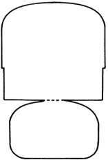
The clear plastic canopy is made from acetate and is a different material than the other plastic parts. It is thinner and more easily softened than the vinyl plastic pieces. Extra special care should be taken when cementing the canopy in place and when painting in the window separation. If these suggestions are followed, you should have no problem with the attachment and painting of plastic parts thus insuring a neat appearing model.
|
|
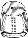
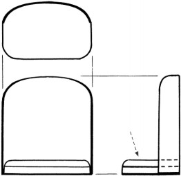
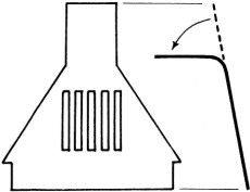
Trim the plastic nose cowl to shape. Refer to special instructions on "Plastic Parts Preparation". At this time, take the larger portion of the clay furnished in the kit and after making the clay soft and pliable by working it with your fingers, carefully press the clay into the inside front and bottom of the cowl as shown in dotted lines on the side view of the model. Work the clay into position so that it fills the particular area. The remaining portion of the clay will be used later for final balance of the model.
Cement the plastic cowl to the front former "Bl" by first beading the immediate inside edge of the plastic cowl with cement and also beading around the edge of "Bl" former. Slip the cowl onto the fuselage and after lining up the cowl carefully, wipe off any excess cement. After the cement has dried, you will note that the edge of the cowl has shrunk and blended itself into the fuselage. A light amount of sanding around the edge will smooth the joint.
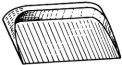
Next, cement the stabilizer-elevator to the fuselage and then cement the fin-rudder into place. Line up carefully, pin if necessary till dry. Cement the wing to the fuselage. Line up carefully and, either rubber band or pin in place till dry. Cement fillet parts "M" to the trailing and leading edge where shown and against the fuselage. Carefully trace and cut out the fairings from cardboard. Carefully
|
shape the cardboard fairing by bending and twisting it until it freely fits into proper position and then cement fairings into place. Pin to hold in position until dry, if necessary. Trim and cement any and all other plastic parts such as radiators etc. into position — refer to plan for locations.
NOTE: To do a neat job of cementing plastic parts to the model, follow this procedure — first, locate the part on the model without cement and while holding it in position, with a very soft pencil, mark around the part and onto the model. Then when cementing part to the model, the part can immediately be positioned without guess-work. Plastic parts should be held in position till dry with pins or rubber bands. If the model is to be only a show model, then any cockpit detail you desire should be incorporated into the model. Also the inside of the cockpit should be painted a light green. After cockpit details are in place, trim the canopy as shown and cement into position on the fuselage. Follow the same procedure as used with other plastic parts.
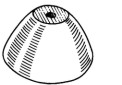
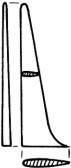
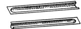
The gear fairings should be sanded smooth, edges rounded and clear doped ready for painting. The plastic spinner should be trimmed and cemented to the plastic propeller. The model is now ready to be painted. Refer to special instructions on painting the model.
|
|
There are two types of fast drying colored dopes you can use on your model. One is Nitrate and one is Butyrate fuel proof. The Butyrate is fuel resistant but the Nitrate is not. You can also use a plastic base type paint like the 410M Railroad paint that is also fuel resistant and fast drying. You can use any of these three types for the rubber and non-flying scale version of the model, but you must use a fuel resistant type if you use a glo-plug engine, because the potent materials in the fuel will soften and dissolve the nitrate dope. This, of course, will spoil your finish.
Generally, the colors on the war planes were of a dull or semi-gloss finish. Most of the dopes are a glossy paint. The 410M Railroad paint has an authentic dull finish and makes for real scale effect when used. The proper colors can be had by inter-mixing the paint colors. Also, the glossy paints can be used and dulled after they are dry by using an abrasive mixed with water, such as Bon-Ami powder. Rub the surface just enough to take away the high gloss and then wash the powder off with clear water.
The painted finish of your model will only be as good as your
|
preparation. The consistency of the paint should be such that it does not dry out while being applied and still not so thin as to run easily. Use a good ½" to ¾" brush and, assuming that the model is clear doped, smooth and clean, proceed as follows: Paint all of the edges first. Paint one half of the fuselage at a time starting at the nose and proceeding to the rear.
Next, paint the top and bottom of one wing panel and stabilizer-elevator and one half of the fin-rudder. When dry, so you can handle the model, paint the remaining half of the model. On the fuselage, brush on all coats the length of the fuselage. On the wing and tail surfaces, brush each alternate coat on in opposite directions, finishing with the last coat running in the same direction as the fuselage.
Apply only enough colored paint to give complete coverage, as colored paint is heavy. Usually, two or three coats is enough. When more than one color is required on a model, finish the lightest color first and the darker color last, because dark colors cover over light better than light over dark. Allow sufficient time between coats for the paint to dry.
|
|
After the model has been painted, ink in the control surface lines — refer to drawings for positions. Apply decals to model in positions shown following instructions on back of decals. Add finish details such as radio mast, struts, etc. Cement gear fairings to gear struts, paint and install wheels as shown.
Tie rubber motor into a double loop and install in fuselage as follows: Tie one end with about 10" of light string. Insert other end into fuselage with nose up, so rubber will go through inside of formers easily. When rubber is at proper former, it can be seen
|
through dowel hole on "L" part. Insert 1/8" dowel through "L" part and through rubber loop. Pull front end of loop through with string. Remove string and slip motor over the propeller hook.
The model can now be balanced at the point shown on the plan by adding the necessary amount of clay to the front and bottom of the cowl. Soften the clay and smooth it on so that it blends with the cowl area. In the event that the model is nose heavy without the additional clay, you can add a small amount of clay to the rear of the model around and behind the plywood tail wheel.
|
|
The wings and tail surfaces should be checked for possible warps. These can be detected by sighting the surfaces from the center of the model, either by looking from the front or the rear. If warps are apparent, follow this procedure in removing them. Warps can be removed by direct dry heat or by moist heat or steam from the spout of a water or teakettle. Steam is more effective for removing warps. With the kettle about half full of water, bring the water to a boil so steam is pouring out of the spout. Now, turn down the heat until the water is, just at or above the boiling point and the steam is floating out of the spout rather than being forced out. Holding the model in a manner that allows you to twist the warped surface and still keep your hands well away from the steam, proceed to remove warp in this manner: Hold the warped area close to the steam and move the area over the steam and around in a circular pattern until you see the covering relaxing or even getting loose. Now, gently twist the surface in the opposite direction and a little more than is needed to remove the warp. Take the model away from the steam, still holding the surface in that state, and hold that way until the surface tightens up again. After releasing the surface,
|
it should have
removed the warp.
If more twist is needed, repeat the procedure until the warp is removed. If you went too far, repeat the procedure, but slightly in the opposite direction.
You are now ready to test-glide your model. If possible, select a grassy area such as a field to test in. Do not test-glide or fly your model on a very windy day as the wind can raise havoc with adjustments and flying, and can also damage your model unnecessarily.
Holding the model by the fuselage and just behind the trailing edge of the wing, thrust the model gently into the prevailing breeze with the nose slightly down. Even better, if you aim the model at a pre-determined spot on the ground about one hundred feet away from you, this will set you up for the proper glide angle to thrust the model. Of course, the model will not glide that far from this height, but it should glide smoothly without veering up or down and touch at about the distance you get by multiplying the height of the launch times ten. As an example, you thrust the model from a five foot height (your height plus the raising of your arm).
|
|
Multiply the five foot times ten and your model should glide about fifty feet. This is an approximate footage as it will vary with the amount of breeze blowing.
If the model dives extremely, raise the rear of the elevator by breathing on it until the glide is good. If the model raises its nose too much or shows signs of "ballooning", depress the elevator to remove this condition. The model should also glide straight. "Breath" the rudder to the right if model goes left and vice versa.
Make the first power flights with about fifty turns on the motor. Wind the motor clock-wise. Hold the model the same way as if you were going to glide it with the tip of the propeller held with your other hand. Release the propeller and thrust the model forward and into the wind with the nose slightly up. The power launch should be no harder than the glide launch because the propeller thrust takes over as soon as you release the model. The model will fly with just a gentle turn to the left. Wind the propeller twenty-five more turns this time and launch. Note the flight pattern. If the model starts to tighten up in the left turn, then "breath" a little right rudder into the model.
|
Keep increasing the winds twenty-five times each flight until maximum turns of two hundred and fifty are reached. Keep adjusting the rudder to the right until, under full power, the model flies either straight ahead or a little to the left and glides to the right towards the end of the flight.
Longer flights can be had if you lubricate the rubber with straight castor oil. Lubricated, you can put three hundred and fifty turns into the motor. By stretching the motor while winding, even more turns can be added. If you wish to increase the turns even more, purchase some ¼" wide T-56 rubber at your hobby store, lubricate, stretch, wind and you can more than double the original turns. With someone holding the model, stretch the rubber about three times its original length, and by holding and supporting the wood thrust button with your thumb and index finger and winding with your other hand, you can put in maximum turns. As you are winding slowly, move towards the model until full turns are stored.
If excessive climbing or "ballooning" is encountered under full power, this can be taken out by breathing the elevator down just a little.
|