

|
Before starting construction of your model, study the plan and construction procedure carefully so that you will have a complete understanding of the step-by-step method of building this airplane. Guillow engineering has provided you with the most up-to-date method for building a real scale flying model but only careful attention to detail will insure the success of your efforts.
Most prize wining models are the results of patience and careful workmanship. You too, can achieve success by following the example of champion model builders — by working slowly and carefully at all times.
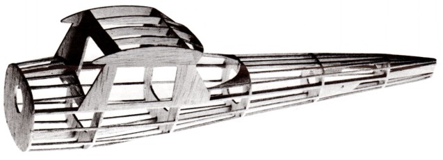
The frame photographs shown on this instruction sheet are actual pictures of the model you are about to build. The line drawings under each photo show the method of frame
|
construction but are not the actual illustrations of the model you are making. In other words, refer to the line drawings for construction procedure — refer to the photos for construction details of your model.
IMPORTANT HINT. Before removing parts from die-cut balsa sheets, lay each one PRINTED SIDE down on a flat surface and sand the exposed side with fine sandpaper wrapped around a sanding block. This will help free any parts not completely cut through and also lighten the overall weight of the model—an important factor for rubber powered flying models. Sand carefully—do not crumple die-cut sheet by working too fast or with too much pressure.
Good luck and good flying!
|
|
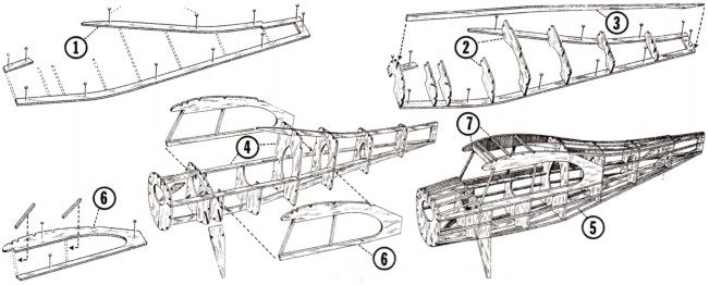
1. Pin top and bottom keel parts "A" over fuselage layout.
2. Cement one each of formers "B" into position on keel — be sure formers are at right angles to keel.
3. Cement side keel "A" into deep notches of formers "B".
4. When dry, remove frame from plan. Cement other halves of formers "B" to center keel; then add remaining side keel. Add former "B-B" if shown.
IMPORTANT NOTE! See Instructions on plan about wire gear attachment. Some models require landing gear attachment before the addition of stringers—others before frame is covered with tissue.
5. Cement 1/16" sq. stringers into their respective notches.
|
NOTE: To obtain uniform tension on fuselage, cement stringers alternately to left and right sides and top and bottom. NOTE: On some models, certain stringers are not cemented in place until parts "H" and "J" are first cemented into position. These particular stringers will be noted as such on the side view of model
6. Add "H" parts to fuselage frame. (For Cherokee, soak "H" parts in water first then cement in place while wet.)
7. Join pilot halves together with plastic cement. Use enamel paint for finish. Install in fuselage as soon as possible. Cement parts "L" into place.
8. Lightly sand fuselage to remove balsa fuzz and excess cement.
|
|
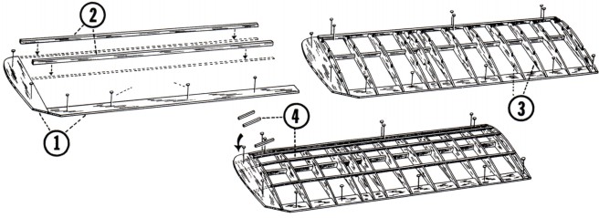
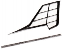
1. Pin to plan, and cement respectively to each other, all "E" parts of left wing.
2. Cement leading edge and spar in position.
3. Cement wing ribs "F" into position between leading and trailing edges and to spar.
|
4. Cement the top 1/16" sq. spars into rib slots. Cement 1/16" sq. stock to tips as shown
5. Follow the same procedure in assembling the right wing half.
6. When dry remove wing frames from drawing plan. Sandpaper the leading edges to shape and gently round all other edges.
|
|
When attaching tissue covering to frames, it is best to use thinned out clear dope as an adhesive instead of cement, or full strength dope. Only apply dope to OUTSIDE edges of areas being covered—do not apply dope to frame work within area covered by section of tissue.
FUSELAGE: First cover any flat surfaces such as sides and bottom of frame. Cover curved areas of fuselage in separate sections — vertically between formers. Dry fit tissue over curved sections to see how much of an area can be covered with one piece of tissue without wrinkling. Cut tissue slightly larger than area to be covered then trim off excess after attaching to frame.
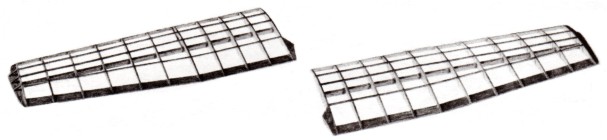
WINGS: Cover bottom of wings with single pieces of tissue. Cover top of wings between root rib and tip rib with one piece of
|
tissue. Cover center sections and tips with separate pieces of tissue.
TAIL SURFACES: Cover both sides of rudder and top and bottom of stabilizer with single pieces of tissue.
DOPING THE COVERED PARTS: After covering is completed and all excess tissue is trimmed off, spray tissue with water from an atomizer and let dry until covering becomes smooth and taut. For best flying performance, the model should be kept light and it is suggested that only one coat of clear dope be applied to the surfaces. (If model is to be used for display only, it can be given several coats of clear dope then finished up with colored dope.) Lightly sandpaper remaining balsa parts and apply one coat of dope to all surfaces.
|
|
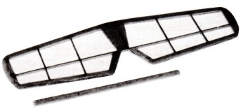
1. Pin to plan, and cement respectively to each other, all rudder parts "C". Cut 1/16" x 3/32" members to size and cement in position.
2. Build stabilizer frame in a similar manner using parts
|
1/16" x
3/32" members.
3. Remove frames from plan and sandpaper lightly, rounding all edges.
|
|
1. Full scale details of a non-flying scale propeller are shown on plan. No material is furnished in the kit for this part but it can be made from other balsa or you can re-work a small gas motor propeller obtainable at your local hobby shop. Use this
prop only for exhibition model.
|
2. Finally add the decals as per instructions on reverse side of decal.
|
|
1. Check wings for possible warps. If warped, correct by holding the warped section over steam from a boiling kettle and twisting gently in the opposite direction until wing is straightened — be careful and don't get scalded!
2. Test glide model over grassy area by gently thrusting model forward from shoulder height. Adjust model for level flight by gently bending stabilizer either up or down to compensate for a dive or climbing stall, ("up" stabilizer for dive — "down"
stabilizer for stall).
|
If model veers right or left, adjust for straight glide by bending rudder in opposite direction of curved flight.
3. Wind propeller 100 turns (clockwise when facing nose of model) and gently thrust into prevailing wind. If model climbs too rapidly or goes into a stall, correct flight by bending rudder slightly to the right to give a climbing right turn. Longer flights can be made after initial tests by winding propeller motor up to 200 turns
|
|
1. With a sharp razor, remove tissue from around notches in wing ribs that receive the wing struts.
2. Carefully cement windshield to fuselage. Pin in place till cement dries if necessary.
3. Cement left wing to fuselage and pin to hold location. Cement strut into notches in wing and t fuselage as shown.
4. Repeat this procedure on right wing.
5. Cement stabilizer to fuselage. Line up carefully. Cement rudder to fuselage also. Cement nose gear to fuselage. (See wire gear layout).
6. Slip wheels on axles and either bend up ends of axles with needle nose plier or put a bead of cement on end of
|
each
axle. (See wheel pants information.)
7. Trim nose cowl to shape and slip over nose of fuselage. Bead all around the edges with cement.
8. Assemble propeller, prop hook, bead and nose bearing as shown on plan. Install rubber motor as follows: Insert one end in fuselage and fasten in place by sliding rear mount (cut from excess axle wire or use round toothpick) through loop and "L" parts. Attach other end of rubber loop over prop hook and slip propeller unit into hole in plastic nose cowl.
9. At this time, balance the model at point shown on plan by placing modeling clay on bottom of nose cowl. Press the clay firmly in place.
|
|
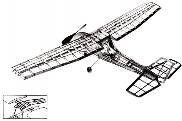
If a stronger wing and fuselage connection is desired use 1/16"birch dowels as shown in sketch. Dowels should be long
|
enough to penetrate second wing ribs. Sharpen ends of dowels first. Line up carefully before cementing wings to fuselage.
|