

|
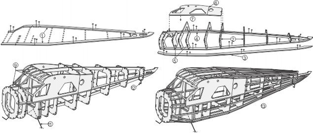
1. Pin and cement respectively to each other, W1 through W3, the 1/8 inch square spar and 3/32” x 1/8” leading edge over the plan.
2. Cement wing ribs (W4 - W6) into position between the leading and trailing edge, making sure that the ribs are at a right angle to the board.
3. Cement the 1/16” sq. stringers into the wing rib slots. Cement short
|
1/16” sq. stringers from W5 to the wing tips as shown.
4. Follow the same procedure in assembling the other wing half.
5. When dry remove wing frames from plan. Sandpaper the leading edge to shape and gently round all other edges.
|
|
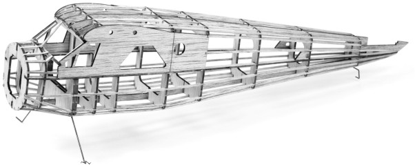
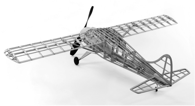
1. Pin to the plan and cement respectively to each other, all center keel parts (A1-A4) and a 1/16” sq. stringer in between A1 and A2.
2. Cement the left side formers F1 through F10 on the center keel (excluding formers F3 and F5 for now, they will go on later).
3. Cement the side keel parts A5 & A6 to one another over the plan. When dry, lightly sand the area where it was glued, on both sides, to ensure that it fits properly in the former slots.
4. Cement side keel (A5 & A6) into the deep notches in the formers, making sure that the formers remain at a right angle to center keel.
5. After the center keel is dry, cement the left side pieces F3 and F5 into place, making sure they are parallel to their counterparts. Keep in mind that only one F3 piece is to be added at this time.
6. Using the cabin template on the plan, lightly score the outside of both A7 parts on the line shown so that the rear portion can crack/bend in to follow the line of the side keel. Glue a 1/16” square support strip to the inside of the canopy along the dotted line on the template for extra support. Note: two A7 pieces should mirror one another when done.
7. Glue A7 into place on fuselage side, lining it up from F7 forward so that it will extend past F3.
|
8. When dry, remove frame from plan and cement the right side formers to the center keel making sure they are parallel to their counterpart. When dry cement the other side keel and A7 piece into place.
9. Cement F11 & F12 into their respective location. When dry cement L1 & L2 pieces in between the top of F4 & F12.
10. Bend the main and tail landing gear wire over layout on plan .
11. Insert the main landing gear wire into the small notch in the center keel that is located in front of the F3 former. Cement in place against F3 making sure that it both sides are even. Using the 2 remaining F3 former halves sandwich the wire, making sure that the formers join together and are parallel to the other set , then cement into place.
12. Cement the tail landing gear wire into place behind F10 and up against the center keel. Cement a 1/16” sq. balsa strip to the wire and the center keel. (See full size side view)
13. Cement 1/16” sq. stringers into their respective notches. Note: to obtain uniform tension on the fuselage, cement the strings alternately from left to right sides and top to bottom. Cement L3 into place by F9.
14. Lightly sand fuselage smooth to remove balsa fuzz & excess cement.
|
|
Before starting to tissue, make sure your parts have dried well and you have sanded your pieces smooth.
Our instructions below use a mixture of white glue and water to adhere the tissue covering to the framework, modelers dope may be used instead if you have it in your workshop.
1. Get a small paintbrush out and mix up a 50% water - 50% white glue mixture in a small cup. Stir it well.
2. Cut a slightly oversized section of tissue apart with some scissors and have ready to glue to frames using the glue mixture.
3. Brush glue mixture onto the perimeter edges of the frame.
4. Immediately set tissue on glued frame BEFORE it has a time to dry and smooth flat as possible with finger tips. When smooth, paint another coat of glue mixture through the tissue (around the perimeter) so you get a good strong bond.
5. When dry, trim off overhanging tissue with modelers knife. Sandpaper can be used if knife is not available. Apply coat of glue mixture to trimmed edges and smooth down any loose tissue with finger tips.
|
FUSELAGE: See diagram on plan for suggested placement. First cover any flat surfaces such as the sides and bottom of frame. Cover curved areas of fuselage in separate sections - vertically between formers. Dry fit tissue over curved sections to see how much of area can be covered with one piece of tissue without wrinkling. Cut tissue slightly larger than area to be covered, then trim off excess after attaching to fuselage frame.
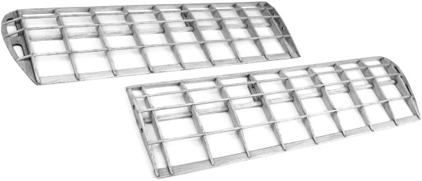
WINGS: Cover bottom of wing with single piece of tissue. Cover top of wing between root rib and tip rib with one piece of tissue. Cover tips with separate piece of tissue.
TAIL SURFACES: Cover the top and bottom of both the rudder and stabilizer with single pieces of tissue.
FINISHING THE COVERED PARTS: After covering is completed and all excess tissue is trimmed off, mist the tissue with water and let dry. This will cause your tissue to shrink a bit and tighten, removing most wrinkles and imperfections, leaving you with a nice smooth surface. For best flying performance, the model should be kept light and it is suggested that only one coat of clear dope be applied to the surfaces. (If model is built for display only, it can be given several coats of clear dope then finished up with colored dope or paint.)
|
|
1. Full scale detail of a non-flying scale propeller is shown on plan. No material is included in kit for this part but it can be made from other balsa or you can re-work a small gas motor propeller accessible at your hobby shop. Use this prop only for exhibition model.
|
2. Finally, add decals (following the instructions on the back of decal) & paint per color scheme on plan.
3. Refer to the painting on the box top and color scheme on plan to add any other desired extra details to your model.
|
|
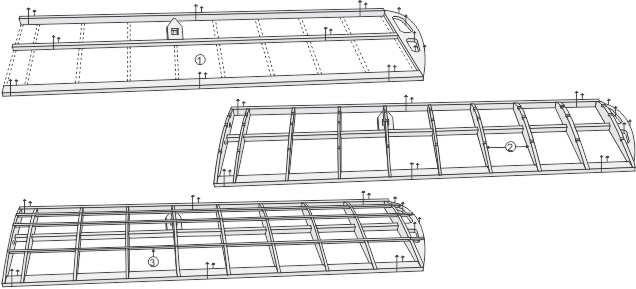
1. Pin X1 & X2 down over above layout
and cement Y1 through Y7(excluding Y4) left halves on top at 90 degree angle. 2. Remove structure from board and cement the right halves on. Then attach Y4 in place. 3. Cement 1/16” square stringers into notches. 4. Cement X3 & X4 into locations seen in photo (note, one left side float and one right side float needed). 5. Carve float tip from scrap balsa block. |
6. Cover the float with tissue paper.
(note: under camber on bottom of Y1, Y2 and Y3)
7. Cement X6 & X7 strut parts together and insert into top notches ... along with X8 strut. 8. Cement X5 rudder on back of float. 9. Attach floats to plane, matching the placement seen in the 3 view drawing above. 10. Cement X9 landing gear braces in between X6 and X8 pieces perpendicular to the floats, connecting them to one another. |
|
1. Check wings for possible warps. If warped, correct by holding the warped section over steam from a pot of boiling water and twisting gently in the opposite direction until wing is straightened. Be careful and not to get burnt!
2. Test glide model over a tall grassy area by gently thrusting model forward from shoulder height. Adjust model for level flight by gently bending stabilizer either up or down to compensate for a dive or climbing stall. ("up" stabilizer for dive - "down" stabilizer for stall). If
|
model veers right or left, adjust for straight glide by carefully bending rudder in opposite direction of curved flight. If your model has moveable parts bend the fin slightly to trim the model flight.
3. Wind propeller 100 turns (clockwise when facing nose of model) and gently thrust into prevailing wind. If model climbs too rapidly or goes into a stall, correct flight by bending rudder slightly to the right to give a climbing right turn. Longer flights can be made after initial tests by winding propeller motor up to 200 turns.
|
|
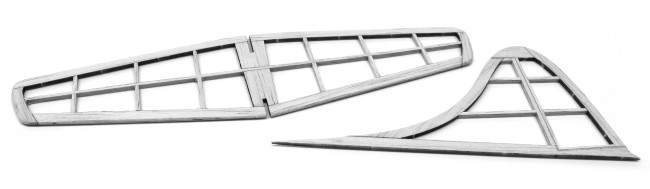
Before starting construction of the tail surfaces you must ask yourself two important questions: First, are you building this model as static display or for flying? If building a flying model be sure to use enlarged FLYING STABILIZER “SF” parts and the 115% over scale stabilizer layout on the back side of the building plan to give your plane a more stable flight. Second, do you want a simple fixed rudder or hinged movable parts? If building movable surfaces be sure not to cement parts together along the hinge lines (see further notes in step 2).
|
1. Rudder, pin to plan and cement all rudder parts ”R” to each other.
2. Cut 1/16” x 3/32” spars to size and cement into position.
NOTE: If making a moveable rudder be sure not to use any cement along the separation line, creating 2 sections; the rudder and the fin. To make the hinge use scrap plastic or an aluminum soda can. Insert the hinge pieces into the spars between the rudder and fin in the locations seen on plan.
3. Build the stabilizer frame in similar manner again cementing the “S” parts to each other and using 1/16” x 3/32” spars.
4. Remove frames from plan and sandpaper lightly, rounding all edges.
|
|
1. Pin F0 over plan and cement L6 & L7 “keys” into place making sure they are at a 90 degree angle to F0.
2. Cut out the plastic parts, putting the 2 small air scoops to the side (used in step 12). Using the L6 and L7 “keys” for placement cement the cowl onto the front of F0 (see diagram on plan). When dry insert into the slots of the F1 formers.
3. Trace window templates onto clear acetate using plan drawings, then cut out of acetate. Carefully cement windshield and other windows to fuselage. Pin in place until cement dries if needed.
4. Cut 1/8” dowels to length as shown on plan. Take the two 3” dowels and insert through the holes in the top of the cabin. Insert the wings onto the dowels and apply a bead of cement.
5. With a modeling knife, remove tissue from around notches on W3 that receive the wing struts.
6. One at a time cement wing strut in notches at bottom of the wing & to fuselage as shown. Then better cement the wings into place.
7. Cement landing gear fairing pieces L4 and L5 into place.
8. Cement stabilizer to fuselage. Line up carefully, making sure it is parallel to wings. Cement a piece of 1/16” stock inside the slot above the stabilizer.
9. Curve the paper elevator cover slightly to allow it to fit smoothly over
stabilizer. Then cement paper cover in place.
|
10. Cement rudder to fuselage, being sure its perpendicular to stabilizer.
11. Cement wheel halves to one another. Slip wheels on axles and either bend up ends-of axles with a needle nose pliers or put a bead of cement on the end of each axle. Wrap paper landing gear fairing around L4 & L5, cement into place.
12. Cement the paper dummy engine into the front of cowl. Cut the exhaust stack from spare household straw and glue into place along with the 2 plastic air scoops (3 view & size side view for placement).
13. Assemble the propeller, prop hook and nose bearing as shown on plan. Note, if you are building a flying model use the 7” propeller. If you are building a static model use either the 4” plastic propeller or carve your own using scrap balsa and the scale drawing shown on the plan.
14. Place the propeller into cowl, as shown on plan. Install rubber motor as follows: Insert one end in fuselage and fasten in place around the rear motor mount (the 1½” long dowel) which is inserted through the "L3" parts. Attach the other end of rubber loops over prop hook and slip propeller unit into hole in plastic nose cowl.
15. At this time, balance the model at the point shown on plan by placing modeling clay to the inside and bottom of fuselage directly behind former "F1." Press the clay firmly in place so it will not dislodge.
|