


|
If you are a beginner, it is strongly suggested that a careful reading of the General Information Sheet enclosed, BEFORE starting model construction, will be of great and lasting benefit. It deals with the techniques of preparing the balsa wood parts for building the various frame structures, the handling and application of tissue as a covering for the frames and, finally, the cutting out and finishing of the individual plastic parts molded on the large sheets of plastic. Although many of the illustrations on the General Information Sheet depict a model other than the PBY (a F-15 Eagle), the methods of model construction are similar for most balsa models. One of the major differences between this PBY-5 kit and other Guillow kits is in the
|
treatment of plans that are divided into "reference" and "cut-apart" sheets. The former are for reading only -the latter are "work sheets" on which the model frames are built after they have been cut into smaller sections. In addition to ease of handling, these cut-apart plan sections provide full size templates of the frame parts.
The step-by-step instructions that follow describe the assembly of a non-flying exhibition model with "fixed" flying surfaces. If you wish to build your model with movable flying surfaces, read the information provided on Plan D, Section 8 and Plan E, Sections 13 and 14 BEFORE starting.
|
|
There are a number of model building tools and accessories needed that are not supplied in the kit. These should be accumulated before starting model construction. Many are available at home - others must be purchased at a local hobby shop. The major items are described on the General Information Sheet. Others include plastic Balsa Fillet Material for
|
filling in gaps in joints, a small model builder wood plane, small model builder hand saw with fine teeth, triangle or square blocks for aligning formers during fuselage assembly, hand drill and bits for drilling holes, and water soluble paints for finishing the model.
|
|
Before starting model construction, it should be decided whether to build it as a "float" plane without landing gear - a PBY-5 - or as an amphibian - a PBY-5A with landing gear. In the latter case, the model can be assembled with the wing floats and landing gear either EXTENDED or RETRACTED. A choice must be made in as much as the wing floats and landing gear are immovable once installed in either position. Implementation of these choices is expanded upon during the various stages of construction.
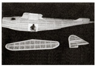
The instructions that follow cover the building of the fuselage, wing, rudder and stabilizer frames in that order. If desired, the rotation can be changed if you wish to build the smaller and simpler rudder and stabilizer frames first. This is easy to do with the Guillow reference and work sheet arrangements.
At the start, a decision should be made whether to build the model with "fixed" or movable flying surfaces Inasmuch as some parts for these items must be modified (trimmed to length, etc.) If the choice is for movable surfaces.
I
|
f using balsa wood cement for joining balsa wood parts, it is recommended that a thin coat of cement be smeared on all contacting surfaces before parts assembly for an extra strong bond. This does not apply to Elmer's Glue-All or instant glue.
Although most of the shaped balsa parts are die-cut, several of the small parts are only printed on the die-cut sheets and must be cut out with a model builders knife or single edge razor blade. This is done to prevent the crushing that often occurs when very small parts are die-cut.
To avoid misplacement or loss of die-cut balsa parts, it is recommended that only the parts for a specific model frame be removed from the die-cut sheets at one time.
Before cutting out the white plastic nacelle covers from plastic sheet #1 be sure and mark the part numbers on the inside surfaces of the parts for identification during model assembly.
|
|
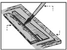
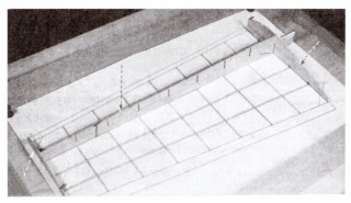
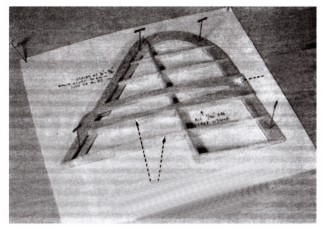
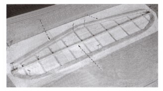
First cut out Section 2 of Plan "D" with the printed fuselage former templates and pin to the workboard with thumb tacks. Next carefully remove all formers (F1 thru F11) from die-cut balsa sheets cutting them loose with the point of a model builders knife if necessary. Lay each former half over its respective template then, with a soft pencil, lightly mark the former number on the face of any half former whose printed number is concealed on the bottom surface. The 3/32" sq. stringer notches in the half formers are only partially die-cut and, to clear them, the sides of the notches must be cut with the point of a razor blade or model builders knife. Pin each right and left half former over its respective template then finish the stringer notches as shown in Drawing No. 1 on page 8.
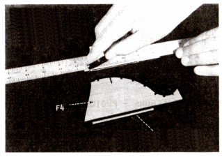
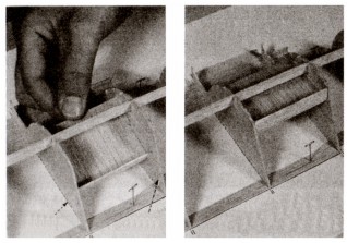
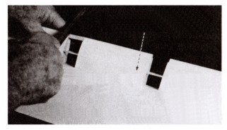
All former halves are die-cut with 1/16" deep shoulders to match the 1/16" thickness of the center keel parts (A1 thru A4). All former halves that are to be cemented to the pinned down center keel (for left side of fuselage) are to be used with the 1/16" shoulders as die-cut. All of the matching former halves (for right side of fuselage) MUST have these 1/16" shoulders trimmed off so that when they are cemented in place, they will fit flush
|
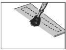
against the center keel and left side formers. Use a straight edge and razor blade to carefully remove these 1/16" shoulders. Photo 1.
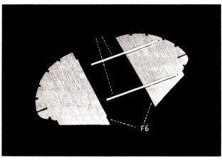
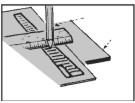
To achieve a positive alignment of the fuselage half formers when they are cemented to the center keel, the following optional step is suggested. Cut and lightly cement two pieces of 1/16" sq. balsa strip to each of the half formers without the shoulders as per templates. Do not cement to the former halves with the shoulders. Photo 2. These strips will provide an exact "in line" alignment when the "shoulder
less" half formers are cemented to the center keel and the first set of half formers. Once the fuselage frame has been completed, the alignment sticks can be "popped off" if not permanently cemented in place beforehand to reinforce the formers.
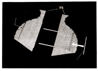
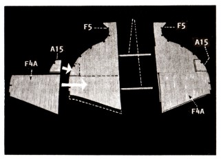
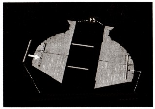
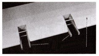
It is VERY important that formers F4 and F5 be treated as shown and described in Section 2. Once the 1/16" sq. alignment sticks have been glued in place, two added 1/16" sq. strips must be glued to F4 (PHOTO 3). Next turn the F5 half formers upside down on the F5 former template and proceed to glue parts F4A and A15 In place on half formers -finally add the two 1/16" sq. strips (PHOTOS 4 and 5).
|
|
A14 and "double" A7 to center keel.
4. Glue side keel parts A5 and A6 together over the Side Keel Layout (Plan D, Section 2) - two required. Glue one of the A5 /A6 side keel into the slots in the sides of the formers noting that it is first scored and cracked upward at former F7 so as to fit into the slots in formers F8, F9 andF10. PHOTO 8.
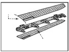
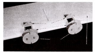
If you intend to build a PBY-5A model, the internal portion of the wheel well structure must be assembled and installed at this time - see Plan F, Section 11 and PHOTOS 9 and 10. Note how the wheel well parts slips under the side keel and between formers F4 and F5. PHOTO 11. (If building a PBY-5 model, disregard this step).
5. Glue chine's A11 and A12 to formers F1 thru F8 - shown in Photo 11 .
6. When all glue joints are dry, carefully remove the frame structure from layout. Now glue the second set of half formers to the other side of the center keel and half formers lightly gluing the 1/16" sq. alignment sticks in place. Assemble and install the right side wheel well structure and then add chines A11 and A12. PHOTO 12.
|
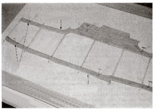
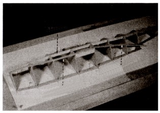
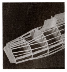
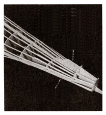
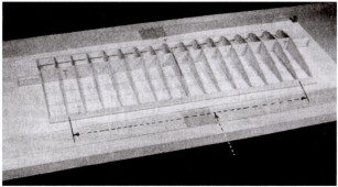
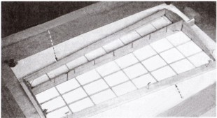
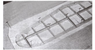
7. The next job is to fit and cement the 3/32" sq. balsa stringers into the notches in the formers. It is best to install stringers in matching pairs - one on the left side and then its opposite on the right side. This will prevent any frame distortion that might result if all or most of the stringers on one side were installed before adding those to the other side. See full size top and side view plans of fuselage frame on Plan "B" for stringer locations. PHOTOS 13 and 14.
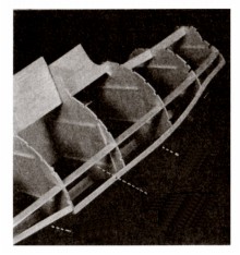
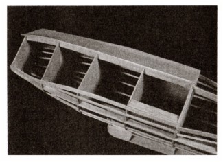
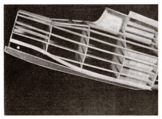
8. PHOTOS 15, 16, 17 and 18 show the attachment of balsa sheeting to bottom of fuselage. The four 1/20" x 2 1/2" x 13 1/4" non-printed balsa sheets are used for this purpose. Selecting one sheet, glue it to the edges of former F4A, the bottom keel and A12 Chine. Photo 15. When dry, "work" the sheeting forward towards former F1
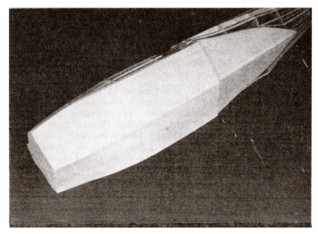
gluing it "as you go" using small common pins if necessary to hold in position until dry. Photos 16 and 17. Cover the other half of the fuselage bottom in a similar manner. Finally, cover the rear portion of the fuselage bottom between formers F5 and F8 with two remaining pieces of sheet stock. Photo 18. Finally add parts A8, A9 and A10. The fuselage frame can now be set aside until it is to be readied for tissue covering and addition of the plastic parts such as cowl, tail cone, gun turret, etc.
|
|
All wing ribs and related parts (PHOTO 19) should be checked against the corresponding templates on Plan D, Section 4 for accuracy of outline, spar notch locations, size, etc. As with the fuselage formers, the 3/32" sq. spar notches in the ribs are only partially die-cut and, to clear them, the sides of the notches must be cut with the point of a razor blade or model builders knife. Pin each rib or partial rib over its respective template then complete the spar notches as shown in DRAWING NO. 2 on page 8 The long pre-cut notches in the ribs that mate with those in the main spars (MS1 and MS2 parts) should permit these parts to slip together without undue force that might result in breakage.
|
Test fit the ribs and main spar notches together before starting frame assembly and, if any notch is too tight, widen slightly with a razor blade. Aim for a smooth fit, not a loose mating. The wing leading and trailing edges should now be prepared as per drawings on Plan D, Section 5.
It is recommended when assembling the wing frames, that the nose and tail ends of the ribs for the right and left wing frame panels be given a SLIGHT taper with sand paper to conform to the slant of the leading and trailing edges as shown in DRAWING NO. 3 on page 8 . Do not shorten ribs when sanding - a slight taper is sufficient. It is suggested that the wing center section frame be assembled before the right and left wing panel frames.
|
|
It is extremely important that the step-by-step instructions that follow be fully understood before starting assembly. Failure to follow the steps outlined may result in an inability to add an important part to the frame after an out-of-sequence construction step has been taken. If you wish to build wing frames with movable ailerons, see separate instructions supplied on Page 4, of this booklet.
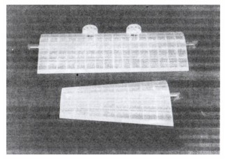
1. Pin and glue the main spar halves (MS1-1/MS1-B) together over the layout on Section 4). Be sure the bottom edges are in a straight line and that the notches in the die-cut balsa parts exactly match those on the drawings. This latter matching is very important since it determines the rib alignments when the ribs are glued to the spars. Any slight variations in notch alignments should be corrected at this time.
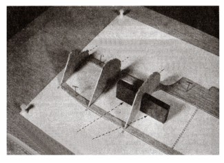
2. Select two of the W1 ribs and glue the W1A and W1B parts between them as shown on the Wing Center Section layout -set to one side. Next select four W1 ribs and glue parts W1C and W1D in position on the W1 ribs being SURE to glue them to the proper sides as shown on the Wing Center Section Layout on Plan C, Section 3. PHOTO 20. This positioning of the W1C and W1D parts is very important since it will be extremely difficult to reposition them once the frame is in the process of being assembled.
|
3. Cut out and pin the Wing Center Section Layout to the work
board and cover with Saran Wrap or equivalent. Pin main spar MS1 over layout making sure that it is at right angles to the layout surface. Glue the outside W1 ribs in position on main spar. PHOTO 21.
4. Prepare then pin the leading and trailing edges against the ends of ribs using alignment gauges W for leading edge, PHOTO 22. Once properly positioned, glue both the leading and trailing edges in place.
5. Now proceed to fit, align and glue the remaining W1 ribs to the main spar MS1 and between the leading and trailing edges. PHOTO 23.
6. The last attachment to the center section wing frame is the 3/32" sq. spars. These are added one at a time and can be "dry fit" first to check the notch widths and depth. If, when sighting along a "dry" positioned spar, a small waiver in alignment is noted, this can be corrected by slightly widening the notch that causes the misalignment. Also, if a notch does not permit a spar to fit down flush with the top or bottom of a rib, it can be cut down slightly deeper with a pointed modeler's knife. PHOTO 24. Finally add the four No.1 small die-cut corner brackets.
|
|
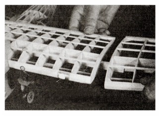
The wing center section frame should be tissue covered before attaching nacelles - see special "Covering the Frames" instructions. As with the wing, all nacelle parts should be individually checked against the templates on Section 12 for size, shape, slot thickness, etc. Before starting assembly, cut the four 3/16" x 3/8" balsa nacelle rails to length. Set aside until needed.
|
.1. Carefully cut away the portions of leading edge between ribs as indicated on plan. The use of a thin blade model builder's saw is recommended for cutting thru the thick leading edges. PHOTO 25.
2. Glue the previously prepared nacelle rails to the ribs and against the wing main spars. Before
gluing the rails permanently in place it is suggested that formers G1 and G2
|
|
be "dry" positioned on the rails to insure precise spacing.
When gluing the rails in position, apply glue generously to create a strong bond between the nacelle rails and wing parts. PHOTO 26. Let glue dry hard. Glue pairs of formers G1 and G2 together and let dry.
|
When dry,
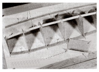
position all G1 and G2 formers on nacelle rails and glue in position. Glue half formers G3 in place on bottom of wing. PHOTO 27. Finally cement G4, G5, G6 & G7 parts to the formers and cut and attach the short 3/32" sq. stringers. PHOTO 28.
|
|
If the choice is for "movable" flying surfaces (ailerons), refer to Plan E, Section 13 for information and wing plan sections that must be cut out and fastened in place over the right and left wing panel layouts. PHOTO 32 shows a completed left wing panel frame with "movable" aileron. The movable aileron is assembled in conjunction with the main frame - not as a separate unit. To build movable ailerons as part of the wing structure, the following steps must be taken during frame assembly. Select die-cut spar MS3 and cut the two hinge slots in it as shown on template. When finished, pin MS3 over its location on the frame layout.
Next cut die-cut wing ribs W5 thru W10 to lengths shown on templates. Select two of the MS4 spars and, after cutting the two hinge slots in each, glue then together to form a double spar. Make two 1/16" thick spacers from scrap balsa (Drawing No. 5) and lightly glue them to the trailing edge face of MS3 as shown. Now, setting the "doubled" MS4 in
|
position on layout lightly glue it to the two spacers pinning in position until dry. Do not glue MS4 to MS3!
Using a thin saw blade, carefully cut away the portion of the trailing edge between ribs W5B and W510 then re-pin in position over the layout. Now glue all rib parts in position between the trailing edge and MS4. When dry, remove the 1/16" sq. spacers between MS3 and MS4 then remove the aileron frame from the main structure. Carve and sand the front of the MS4 spar to the rounded shape shown by the aileron sections.
Cut the plastic hinges from clear plastic sheet. Clear the hinge slots in MS3 and MS4 and, thru them, make thin incisions in ribs W5, W5A, W9 and W9A to take the hinges. "Dry fit" hinges in the MS3 and MS4 hinge slots and, once properly fitted, set hinges and aileron frame aside until later. Drawing No. 6.
|
|
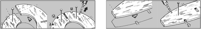
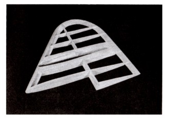
To build a one piece stabilizer, first cut the stabilizer ribs free of the die-cut balsa sheets then check them against the corresponding templates on Plan D, Section 10 for size, etc. Cut them into the quarter sections as per drawing and set to one side.
1. Remove parts SI, S2, S3, and S4 from the die-cut balsa sheets then pin and glue them together over the Stabilizer layout. PHOTO 33.
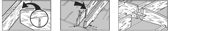
2. Cut and add the pieces of 1/16" sq. balsa strips between parts SI, S2, S3 and S4. PHOTO 34.
3. Cut and glue the 1/8" x 3/16" strip stock over the SI/S2 parts. Add
|
the
1/16" x 5/32" center spar cap over center spar. PHOTO 35.
4. Glue one set of the quarter ribs over the 1/16" sq. strips between the leading edge, center spar and trailing edge. PHOTO 36.
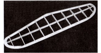
5. When dry, remove frame from layout and glue matching parts to the opposite side. Finally sand the stabilizer tips and leading edge to shapes indicated by the partial front view and sectional drawing on plan. PHOTO 37.
Except for a final sanding the frame is now ready for tissue covering.
|
|
A stabilizer with movable elevators is built much like a one piece unit except for the few extra parts required during assembly.
1. Refer to Plan E, Section 14 for the plan segments that must be cut out and taped or glued to the Stabilizer Layout on Plan C, Section 9. Plan B shows a completed stabilizer drawing with the left elevator as part of the frame work.
2. Cut the stabilizer ribs from the die-cut balsa sheets and treat them as per the instructions in Section 10, labeled "cutting apart ribs for movable elevators" - set to one side. Next cut out the four extra parts for movable elevators on the die-cut balsa labeled S5B and S9B.
3. Remove parts SI, S2, S3 and S4 from die-cut balsa sheets then pin and glue them together over stabilizer layout.
4. Cut and assemble all of the 1/16" sq. balsa strips that make up the "core frame" including movable elevator portions. Note the 1/16" sq. temporary "spacers" between center spar and elevators that are lightly
|
"tack" glued to
the, frame parts.
5. Glue the 1/8" x 3/16" balsa strips to S1/S2 and the 1/16" x 5/32" cap strips to center spar and forward edges of elevator frames.
6. Glue one set of the quarter ribs to all of the 1/16" thick core frame parts including the movable elevator portions. When dry remove frame from layout and glue the matching parts to the other side. When dry, sand the stabilizer tips and leading edge to shape.
7. Cut the two elevators free of the rest of the frame where indicated on layout removing the temporary spacers at the same time.
8. Finally, cut out the plastic elevator hinges and locate placements on both the main frame and elevators. Using a thin knife blade, cut the hinge slots in the 1/16" thick core frames of both the stabilizer and elevators. Test fit together hinges and frames then set to one side - do not glue together at this time.
|
|
The making of the wing floats (Section 16), propellers (Section 17), bombs (Section 18), wing struts (Section 19), and machine guns (Section 20) is
|
described in detail in each sectional area. They can be made/assembled in any order prior to final model assembly,
|
|
A frame with movable rudder is assembled on the two piece layout drawing on Section 8 identified as Core Frame Layout. The nearby Completed Frame drawing provided is for reference
only and shows
|
the fully
assembled structure and location of various parts. It is not provided for "layout" purposes. Accompanying the drawings in Section 8 are all of the instructions necessary for assembling the two piece vertical tail frame.
|
|
The model can be covered either with the tissue supplied in this kit or with the new lightweight iron-on films available at most hobby dealers. Instructions for applying this material is supplied by the manufacturer. The instructions that follow pertain ONLY to a tissue covered model.
Drawing No. 6 shows the frames after being tissue covered.
It is important to note that many of the assembly photographs that follow these instructions show the frames without tissue covering. Nonetheless, all frames should be covered as illustrated because it is extremely difficult to apply tissue covering to the framework of an assembled model. A mixture of white glue (such as Elmer's Glue-All) and water is the adhesive recommended to fasten tissue to model frames. Of course model airplane dope, the old standby, can be used for the same purpose but its use is more difficult and less desirable because of its chemical composition. Refer to PHOTOS 10 thru 16 and related copy on the General Information Sheet for tips on covering tissue covered model. A 50% glue-water solution makes an excellent tissue adhesive. Because of the stringer, rib and former construction use a narrow 1/4" or 1/2" wide brush to spread the glue mixture.
FUSELAGE: Before starting to cover the fuselage, cut the nose cowl (P1) and nose gun turret (P6) from the vacuum formed plastic sheets. PHOTOS 48 and 49. (BE SURE and read the instructions "Preparing the Plastic Parts" that follow before cutting out P1 and P6).
Test fit P1 and P6 over former F1. If the fit is a bit too snug, lightly sand the former perimeter until the parts fit properly in position. If too loose, tape thin strips of masking tape to the former edges to fill in any gaps. Now set P1 and P6 aside until model is ready for assembly.
If building a PBY-5 model, disregard the instructions in the following paragraph in as much as they only pertain to a PBY-5A.
|
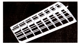
Cut out the J7 wheel well covers from the cardstock sheet. Pin or tack glue them in place over the wheel well areas then, with a soft pencil, mark the portions of the stringers that appear in the wheel well opening that are to be cut away - remove the J7 parts and set to one side. Now carefully cut away the portions of stringers so marked for elimination then glue the J7 parts back in position on the fuselage frame.
Cover the fuselage in sections as shown starting from the front or former F1 and covering vertically between formers. The grain of the tissue should run lengthwise with the fuselage. (The grain of the tissue runs with the width of the tissue sheet as you receive it in the kit). Wing: Cover the top and bottom of wing frames in sections shown by line drawings. The grain of tissue must always run
span wise on the wing.
Tail Surfaces: The rudder can be covered on each side with single pieces of tissue. Tissue grain should run from the base to tip. The stabilizer is covered in a similar manner - single pieces for both the top and bottom of frames. PHOTO 45.
After the frames are covered they should be wet with water by using an atomizer or brush which will cause the tissue to sag temporarily. When tissue covered frame has THOROUGHLY dried, brush a prime coat of 40% glue and 60% water over all surfaces. This will cause the tissue to sag again but, when dried out, the covering should become taut over the entire framework and be ready for the final color coats at a later stage. PHOTOS 46 and 47.
At this time cut out the small fuselage window areas (J18 thru J22) from cardstock sheet and glue them directly to the tissue covered fuselage frame. When painting the fuselage later on, the "window" portions of the J parts should be painted black.
|
|
These cardstock parts ( on J11, J12 and J13) should only be on movable flying surfaces - not on fixed surfaces. See Drawing No. 7 for
|
method of
simulating the rib impressions visible in actual aircraft. The "J" parts are glued directly to the flying surface frames without any tissue covering.
|
|
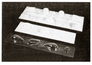
Before using the vacuum formed plastic parts, wash them with soap and water to remove any trace of lubricant used for molding the parts. Any lubricant on a part will mar the finish when paint is applied later on.
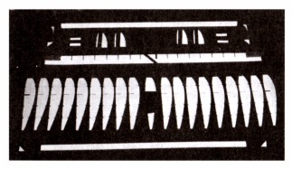
The opaque (non-transparent) plastic parts should each be lightly numbered with a soft lead pencil then cut apart with a pair of scissors (a part number is adjacent to each plastic part). Two pages of the enclosed "Balsa Model Kit Catalog" is devoted to the cutting, cementing and painting of Guillow vacuum formed plastic parts. If not familiar with these techniques, it will pay to read the information supplied before cutting out the parts.
Using the point of a model builders knife or a single edged razor blade, score the plastic part as close as you can at the trim points. The score should be deep by not through. Score twice if necessary. After
|
scoring
gently bend the excess material back and forth until it breaks away. Now sand all the edges smooth. The opaque plastic parts are now ready to be attached to model frames. The clear plastic parts are made of acetate that is a different material than used for the opaque plastic parts. Extra special care should be taken when cementing clear plastic parts in place and when painting in the window separations since a smear of cement over a window will mar its clarity. Use a plastic cement when joining the matching halves of parts that require joining before being added to model. After cement has dried, lightly sand the joints for a smooth finish. PHOTO 49 shows all plastic parts cut to shape and ready for attachment to model frames. They are glued to the tissue covered frames BEFORE the frames are painted and assembled. Use contour putty to fill any gaps between matching halves or between a plastic part and the model frame work. (Contour Putty is available at most hobby shops).
|
|
Although PHOTOS 52 thru 56 show "uncovered" frames, all should be tissue covered PRIOR to assembly unless building a model with a "skeleton" frame work.
Cut out the cardstock cockpit interior (J4) , fold and glue together. When complete, insert and glue in cockpit opening. Cut out the two cardstock waist gun turret bases (J3) and glue to fuselage. Glue the waist gun blisters (P7 and P8) to fuselage. Add machine guns. Attach cockpit canopy. (P9)
Glue the assembled main gear units in wheel wells. PHOTO 52. If building a model with retracted main gears, mount the main wheels in wheel wells.
Glue the nose gear wheel to bottom of fuselage. PHOTO 53.
Add cardstock "doors" (J4).(Omit for "retracted" gear model) Next cut
|
out
cardstock platform (J1) and glue to top of nose cowl. (P1) Prepare nose gun turret (P6) with machine gun and glue to nose cowl over J1. Cut out J2 and glue to top of P6 and fuselage.
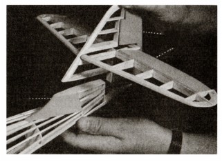
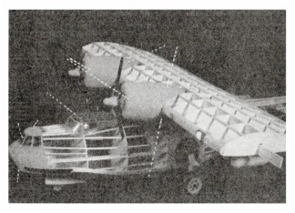
Glue the stabilizer to rudder and, when dry, glue the combined unit to the fuselage. PHOTO 54. Attach motor cowls (P12) to nacelle housings - add oil coolers, (P13). Attach propellers to motor cowls. Attach wing center panel to wing pylon. PHOTO 55. Join outboard wing panels to center panel either as a temporary or permanent connection. PHOTO 56. Finally add the four wing struts, propellers, bombs, sponsons, radio masts/antenna and remaining "J" parts.
|
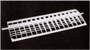
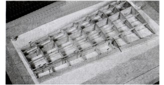
Assembled internal wheel well unit ready for installation.
|
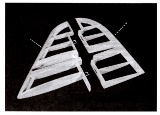
At this time a decision should be made as to whether or not you plan to build your model with "fixed" or "movable" flying surfaces. If the choice is for "fixed" surfaces, the right and left wing panel frames can be
|
assembled on
the layouts (Plan C, Section 6) in exactly the same manner as described for building the wing center section - see PHOTOS 29, 30 and 31.
|
|
The directions supplied in Sections 11 and 15 for making the landing gear units are quite explicit and, in conjunction with PHOTOS 50,
51-A and 51-B,
|
should enable you to successfully complete the projects. PHOTOS 6 and 7 on the General Information Sheet show how to bend wire patterns to shape.
|
|
Tissue covered frames and plastic parts can be painted with water based paints available at a local hobby shop. It is easy to apply, has good coverage and can be cleaned up with plain water - especially for cleaning brushes, spilled drops, etc. Of course, regular model airplane dope can be used for painting purposes but we consider water based colors "safer" and easier to apply and use them in our model development work.
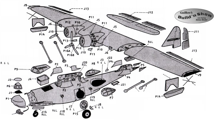
IMPORTANT! Before any painting, the following individual plastic parts should be located on the tissue covered frames then glued in place, (P1, P2, P3, P4, P5, P1O and P11) -See Plan "B". Also IMPORTANT- if building a model with extended gear for display on a table or flat surface, added weight at the nose will be required to balance model. The bar of clay in kit is to be used for this purpose. "Work" clay in your hands until pliable then smear to the inside walls of nose cowl P1 BEFORE
gluing it to former F1. (Clay weight not required for a PBY-5 model or PBY-5A with gear retracted.) Generally, war plane colors had a dull finish and can be purchased at most hobby shops. Follow the manufacturer's instructions when using water based paint. Use a good 1/2" to 3/4" brush and proceed as follows: Paint one half of the fuselage at a time starting at the nose (F1) and proceeding to the tail (F11). Next paint one side each of the wing frames, stabilizer and rudder.
|
When thoroughly dry, paint the other side of each unit.
On the fuselage, brush on all coats the length of the fuselage. On the wing and tail surfaces, brush each alternate coat on in opposite directions, finishing with the last coat running in the same direction as the fuselage. Apply only enough colored paint to give complete coverage -usually two or three coats are sufficient. When more than one color is required, finish the lightest color first and the darker color last, because dark colors cover light better than light over dark. Allow sufficient time between coats for the paint to dry.
When painting the "ribbing" in the canopy and nose and waist gun turrets, you will find it easier to apply the paint on the inside of the part rather than the outside as it is easier to control paint line widths with "inside" painting.
Paint wheel well interiors black - also part A18 of assembled main gear units. After the model parts have been painted add the control surface lines (ruling pen and ink or thin black tape) and decals. Refer to Plan A for the location of these trim items.
|
|
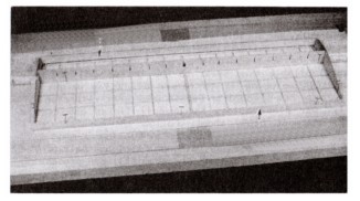
1. Cut out the Fuselage Layout (Plan "C", Section 1). Lay on
work board, cover with Saran Wrap or wax paper then fasten in place with thumbtacks.
2. Remove center keel parts A1, A2, A3 and A4 from die-cut sheets and pin and glue them together over layout. PHOTO 6.
|
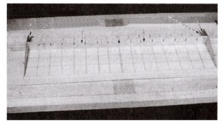
3. Starting with F1, glue all of the left side half formers to the center keel "squaring" them up with a small triangle (or square blocks) so that they are exactly at right angles (90°) to the center keel. They must be supported in this position until the glue has dried hard. PHOTO 7. Now glue parts A13,
|
|
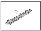
A one piece rudder is assembled on the layout provided on Section 7. First cut out or remove all of the rudder parts on the single die-cut balsa sheet - set to one side after checking size, etc.
1. Pin and glue together rudder parts Rl, R2 and R3 over Rudder Layout. PHOTO 39.
2. Cut and glue together the rest of the 1/16" thick "core frame" from 1/16" sq. balsa strips. PHOTO 40
3. Glue 1/8" x 3/16" strip over R1 and one of the R4 parts over the
|
1/16" sq.
center spar. PHOTO 41.
4. Glue one set of the quarter ribs over the 1/16" thick core frames parts. When dry glue one of the R11 parts in place holding in position with common pins until dry. PHOTO 42.
5. Remove frame from layout and glue the matching parts to the opposite side. When dry, cut off the "projection" on the leading edge then sand the frame to the streamlined shape shown on Plan B. PHOTO 43.
|