

|
There are a number of model building tools and accessories needed that are not supplied in the kit These should be accumulated before starting model construction. Many are available at home - others must be purchased at a local hobby shop. The major items are described on the General Information Sheet. Others include plastic Balsa Fillet Material for
|
filling in gaps in joints, a small model builder wood plane, small model builder hand saw with fine teeth, triangle or square blocks for aligning formers during fuselage assembly, hand drill and bits for drilling holes, and water soluble paints for finishing the model.
|
|
The instructions that follow cover the building of the fuselage, wing, rudder and stabilizer frames in that order. If desired, the rotation can be changed if you wish to build the smaller and simpler rudder and stabilizer frames first. This is easy to do with the Guillow reference and work sheet arrangements.
At the start, a decision should be made whether to build the model with "fixed" or “movable” flying surfaces because some parts for these items must be modified (trimmed to length, etc.) if the choice is for movable surfaces. Also at this time a decision should be made whether to build the fuselage with a "D" or "J" model nose turret - see Plans A and E.
If using balsa wood cement for joining balsa wood parts, it is recommended that a thin coat of cement be smeared on all contacting surfaces before part assembly for an extra strong bond. This does not apply to Elmer's
|
Glue-All or instant glue.
Although most of the shaped balsa parts are die-cut, several of the small parts are only printed on the die-cut sheets and must be cut out with a model builders knife or single edge razor blade. This is done to prevent the crushing that often occurs when very small parts are die-cut.
To avoid misplacement or loss of die-cut balsa parts, it is recommended that only the parts for a specific model frame be removed from the die-cut sheets at one time.
Before cutting out the white plastic nacelle covers from plastic sheet #1 be sure and mark the part numbers on the inside surfaces of the parts for identification during model assembly.
|
|
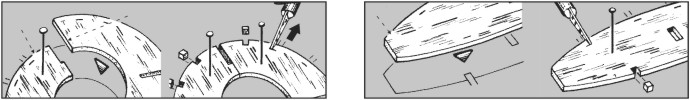
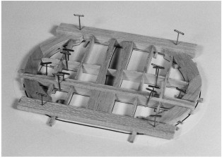
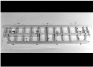
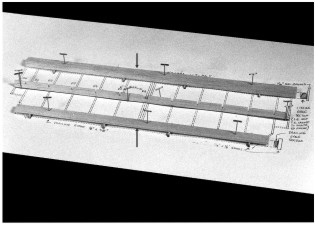
First cut out Sections 6 and 7 of Plan "D" with the printed fuselage former templates and pin to the workboard with thumb tacks. Next carefully remove all formers (B1 thru B15) from die-cut balsa sheets cutting them loose with the point of a model builders knife if necessary. Lay each former half over its respective template then, with a soft pencil, lightly mark the former number on the face of any half former whose printed number is concealed on the bottom surface. (Note: if building a "J" model, use former B1A instead of B1 - see Plan E, Section 14). The 3/32" sq. stringer notches in the half formers are only partially die-cut and, to clear them, the sides of the notches must be cut with the point of a razor blade or model builders knife. Pin each right and left half former over its respective template then finish, the stringer notches as shown in Drawing No. 1 on page 8.
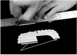
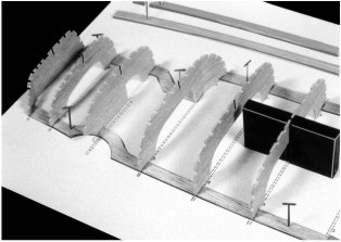
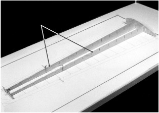
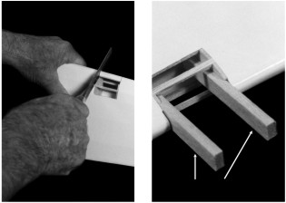
All former halves are die-cut with 1/16" deep shoulders to match the 1/16" thickness of the center keel parts (A1 thru A5). All former halves that are to be cemented to the pinned down center keel (for left side of fuselage) are to be used with the 1/16" shoulders as die-cut. All of the matching former halves (for right side of fuselage) MUST have these 1/16" shoulders trimmed off so that when they are cemented in place, they will fit flush against the center keel and left side formers. Use a straight edge and razor blade to carefully remove these 1/16" shoulders. Photo 1. To achieve a
|
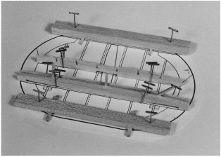
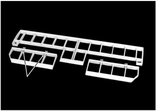
positive alignment of the fuselage half formers when they are cemented to the center keel, the following optional step is suggested. Cut and lightly cement two pieces of 1/16" sq. balsa strip to each of the half formers without the shoulders as per templates. Do not cement to the former halves with the shoulders. Photo 2. These strips will provide an exact "in line" alignment when the "shoulderless" half formers are cemented to the center keel, and the first set of half formers. Once the fuselage frame has been completed, the alignment sticks can be "popped off" if not permanently cemented in place beforehand to reinforce the formers.
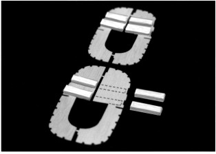
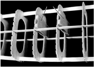
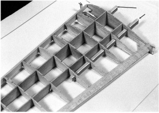
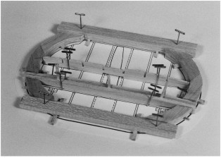
There are eight 3/16" x 3/8" blocks that support the wing rails when the latter are inserted into the fuselage. They must be cut to length and cemented to the FRONT of half formers B7 and B8 at this time. Position them precisely on the former halves using a spare piece of 3/16" x 3/8" stock as a spacer between the two blocks. Do not make the fit so tight that the spacer will not slide easily between the blocks. Photo 3.
Next cement part B3B to front of former B3A then add the 1/16" sq. strips. Finally, score/cut the bottom portion of B1. Bend as shown in side view then cement in position.
|
|
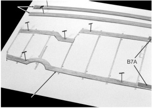
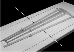
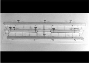
1. Cut out the Fuselage Layout (Plan "C", Section 1). Lay on workboard then cover with Saran Wrap or wax paper fastening in place with thumbtacks. Remove center keel parts A1, A2, A3, A4, and A5 from die-cut balsa sheets and pin and cement them together over Fuselage Layout. Photo 4.
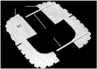
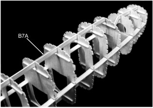
2. Cement two B7A former spacers onto the A2 and A4 keel parts. These spacers set the positions of half formers B7 and B8 that in turn align them exactly with the wing frame rails that slide into the fuselage during model assembly.
3. Starting with B1 or B1A, cement all of the left side half formers to the center keel "squaring" them up with a small triangle (or square blocks) so that they are exactly at right angles (90°) to the center keel. They must be supported in this position until the cement has dried hard. Photo 5.
4. Next pin and cement one set of side keel parts A6 and A7 over the Side Keel Layout. (Shown in Photo 4). When dry, remove from layout then join the second set of A6/A7 parts over the layout in a similar manner.
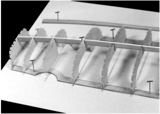
5. Cement one of the completed side keels into the deep notches in the half formers B1 through B15 after it has been scored on the bottom, crack and bend slightly upward at former B11 as shown in the fuselage drawing on Plan "B". Photo 6.
6.Carefully remove the frame structure from fuselage layout. Cement
|
former B3A to back of former B3 with side notch in place on side keel. Cement the remaining half formers to the center keel and first set of half formers. Photo 7.
7. Cement the second side keel to the second set of half formers.
8.Cement the Wing Rail covers over the 3/16" x 3/8" blocks on formers B7 and B8. Photo 8.
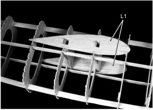
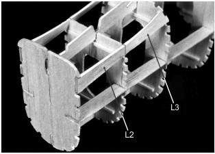
9. Fit and cement wing root parts L1 and stabilizer supports L2 and L3 to both sides of the fuselage frame. Photo 9 and 10. Dip parts L3 in water before cementing in place to aid fit to former B14. (Yes, you can cement "wet" balsa with model cement).
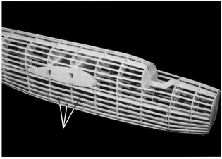
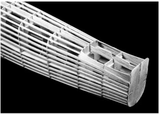
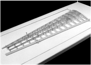
10. The next job is to fit and cement the 3/32" sq. balsa stringers into the notches in the formers. It is best to install stringers in matching pairs – one on the left side and then its opposite on the right side. This will prevent any frame distortion that might result if all or most of the stringers on one side were installed before adding those to the other side. See full size top and side view plans of fuselage frame on Plan "B" for stringer locations. Photos 11 and 12.
The fuselage frame can now be set aside until it is to be readied for tissue covering & addition of the plastic parts such as cowl, tail cone, gun turret, etc. and B7A over the 3/16"x3/8" blocks on formers B6 and B7 Photo 8.
|
|
The right and left wing panels are similar and can be assembled individually or both at the same time if desired. The instructions that follow describe the
|
left wing frame assembly (Plan "B") but are equally valid for the right wing.
|
|
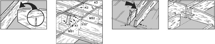
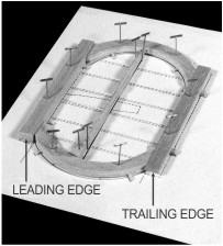
All wing parts should be checked against the corresponding templates on Section 8, Plan "D" and the right and left wing layouts (Section 4 and 5, Plan "C") for accuracy of outline, notch locations, size, etc. As with the fuselage formers, the 3/32" sq. spar notches in the ribs are only partially die cut and, to clear them, the sides of the notches must be cut with the point of a razor blade or model builders knife. Pin each rib or sub-rib over its respective template then finish the spar notches as shown in Drawing No. 2. The long notches in the ribs that mate with those in the main spars (MS1 and MS2 parts) should permit these parts to slide together without undue force that might cause breakage. Test fit the parts together before starting frame assembly and if any notch is too tight widen it slightly with a razor blade. Aim for a smooth fit, not a loose mate. The leading edge (1/4" x 5/8" x 22" stick) should be tapered and rounded as shown and described in Section 8, Plan "D". The pre-cut trailing edge will need a slight tapering from the root rib (F1) to wing tip to precisely fit the tail ends of the ribs (from 1/4" at rib
|
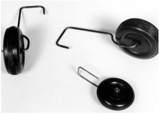
F1 to 3/16" at rib F16). This can be done either before or after it is cemented to ribs. It is recommended that the nose and tail ends of ribs be given a slight taper with sandpaper to conform to the slant of the leading and trailing edges as shown in Drawing No. 3. Do not shorten ribs when sanding - a slight taper is sufficient. You have the choice of installing the extended main landing gear as shown on Plan "A" or a dummy retracted gear (plastic part No. P25) which is cemented directly to the bottom of the wing as part of the final model assembly. For extended gear, assemble it as shown in Plan "F", Section 12. Enlarge the axle holes in the plastic half wheels with a 3/32" bit. Next cement two Wheel Core parts together then, when dry, cement them between a pair of plastic wheel halves. When dry, sand the core flush with plastic wheel halves. Finally, assemble gear, wheel and small plastic lock washers. The nose gear can be assembled at this time. Cut and bend the wire axle unit to shape them and assemble the two wheel halves and wire gear as illustrated.
|
|
IIt is extremely important that the step-by-step instructions that follow be fully understood before starting assembly. Failure to follow the steps outlined may result in an inability to add an important part to the frame after an out-of-sequence construction step has been taken. If you wish to build wing frames with movable ailerons, see separate instructions supplied elsewhere in this booklet before starting construction.
1. Pin and cement the main spar halves (MS1-A/MS1-B and MS2-A/MS2-B) together over their layouts on Section 4. Be sure the bottom edges are in a straight line and that the notches in the die-cut balsa parts exactly match those on the drawings. This latter matching is very important since it determines the rib alignments when the ribs are cemented to the spars. Any slight variations in notch alignments should be corrected at this time.
2. Cement parts F3A/F3B to rib F3; cement parts F4A/F4B to rib F4 aligning them carefully as per templates on plan. Next cement parts F7A/F7B to rib F7; parts F8A/F8B to rib F8. Cement plywood parts K2 to rib F4 and K3 to rib F5. Be sure all of the above parts are cemented to the proper sides of the ribs since it will be difficult to reposition them once the frame is in the process of being assembled. Consult the Top View of Left Wing on Plan B for the correct locations of the above mentioned parts on the respective ribs.
3. Pin Left Wing Layout (Section 4) to the workboard. Special Note - if building model with movable ailerons, cut out the movable aileron drawings (see Plan F, Section 11) and tape or cement them to the left and right wing
|
layouts and wing plan. Also read the "Installing Movable Aileron" instructions that follow these wing construction directions.
4. Cover Left Wing Layout with Saran Wrap or similar material. Pin the main spars (MS1/MS2 parts) over layout making SURE they are at right angles to the layout surface. Slide ribs F1 and F16 into position on main spars lining them up carefully and making sure the bottom of the ribs between the main spars rest flat on the layout. Cement in place. Photo 13.
5. Position and pin the leading and trailing edges against ribs F1 and F16 first blocking them up to the proper height with die-cut alignment gauges W, X, Y and Z. The nose and tail ends of the ribs should now line up with the flat edges of the leading and trailing edges. If there is more than a slight variance, raise or lower the leading and trailing edges slightly until they match with the rib ends. Once the proper positioning has been achieved, cement and pin the leading and trailing edges to the F1 and F16 rib ends. Photo 14.
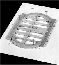
6. Now proceed to fit, align and cement ribs F2 thru F15 to the main spars and leading and trailing edges making sure the rib ends and the leading edges and trailing edges line up correctly. The triangular corner brackets E1 and E2 can be cemented against the F1 rib and the leading and trailing edges. Photo 15.
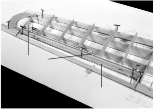
7. Cut the two 3/16" x 3/8" Wing Rail Spars to length, (see Plan B) then
|
|
"thread" them thru the rectangle holes in ribs F1 through F5 and F6. Cement in place. Photo16.
8. Remove the partially completed wing frame from the layout. Cement the two vinyl K1 parts and 3/32" sq. balsa strip between ribs F4 and F5 as shown on Plan B. (See Drawing No. 4) When completed, this unit forms a cell into which the main landing gear wire will be slipped during model assembly. As designed, the gear can be permanently fastened to the wing or, if desired, be omitted and replaced by the plastic dummy retracted gear provided in kit to simulate in-flight appearance.
9. The last attachment to the wing frame is the 3/32" sq. spars. These are added one at a time and can be "dry fit" first to check the notch widths and depth. If, when sighting along a "dry" positioned spar, a small waver in alignment is noted, this can be corrected by slightly widening the notch that causes the misalignment. Also, if a notch does not permit a spar to fit down flush with the top or bottom of a rib, it can be cut down slightly deeper with a
|
pointed modeler's knife. Photo 17. The spars run from ribs" F1 to F16.
10. Fit and cement wing tip parts E3 to the leading and trailing edges and to where it contacts rib F16. Center it between the leading and trailing edges before the cement hardens then set frame aside until the cement bond is firm. Add short spar lengths from rib F16 to tip.
11. The excess leading and trailing edge lengths can now be cut off at one end to form the finished wing tip and at other end flush with the face of rib F1.
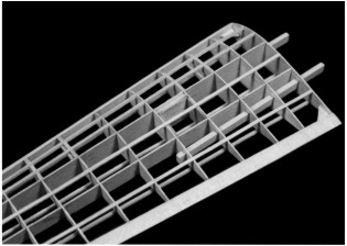
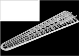
12. By carving and sanding, blend in the leading and trailing edges from rib F16 to the contact areas on E3. Also sand the 3/32" sq. spars from rib F16 to blend into the tip. Trim off the "leveling spurs" on bottom of ribs and sand smooth. At this stage, except for a final sanding, the left wing frame is complete and ready for addition of the inboard and outboard nacelle structures. Photo 18. The right wing frame can now be constructed in a similar manner.
|
|
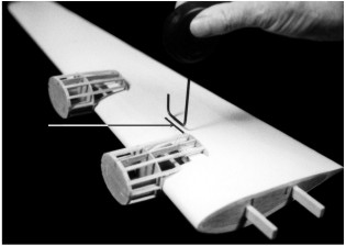
1. Carefully cut away the portions of leading edge between ribs F3 and F4 and between ribs F7 and F8 as indicated on plan and Sections 9 and 9A. The use of a thin blade model builder's saw is recommended for cutting through the thick leading edge. Photo 19.
2. Cement the previously prepared nacelle rails to the ribs and against the wing main and rail spars. Before cementing the rails permanently in place it is suggested that formers G1 and G2 be "dry" positioned on the rails to insure precise pacing. When cementing the rails in position, apply cement generously to create a strong bond between the nacelle rails and wing
|
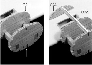
parts. Photo 20. Let cement dry hard. Cement pairs of formers G1 and G2 together and let dry. When dry, position all G1 and G2 formers on nacelle rails and cement in position. Photo 21.
3. Cement half formers G1A and G2A in place on bottom of wing. Photo 22. Finally cement the OB and IB parts to the formers then cut and attach the 3/32" sq. stringers. Photo 23. (This picture also shows how the main landing gear is installed in the bottom of wing). Add right wing nacelle frames in a similar manner
|
|
Cut the movable aileron drawings from Section 11 and tape or cement them to the wing layouts on Plan C, Sections 4 and 5 and to the wing frame drawing on Plan B. IMPORTANT! Do not cut out the drawings until after reading the instructions on Plan E, Section 14 about the installation of a "J" Model nose turret on nose of fuselage appearing on the opposite side of Plan F.
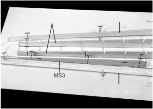
To build movable ailerons as part of the wing structure, the following steps must be taken during frame assembly as outlined below. Following Step 1, 2, 3 and 4 of the left wing frame assembly instructions, select die-cut spar MS3 and cut the two hinge slots in it as shown on template. When finished, pin MS3 over its location on the frame layout with "leveling tabs" touching layout and the thin end towards wing tip. Photo 24.
Next cut die-cut wing ribs F11 thru F15 to lengths shown on templates. Cut out the aileron ribs F10A thru F16A from printed balsa sheets then set aside until needed. Now turn to and complete steps 5 thru 7.
Before proceeding to step 8 select two of the MS4 spars and after cutting the two hinge slots in each, cement them together to form a double spar.
Make two 1/32" thick spacers from wood or cardboard (Drawing No. 5) and lightly cement them to the trailing edge face of MS3 as shown. Now, setting the MS4 in position on layout, lightly cement it to the two spacers pinning in
|
position until dry. Do not cement MS4 to MS3! Now proceed to step 8. Using a thin saw blade, carefully cut away the portion of the trailing edge between ribs F10 and F16 then re-pin the wing frame in position over the layout.
Two pieces of 1/18” x ¼” stock are provided for the movable; aileron trailing edges. Both should be tapered to conform to the main trailing edges.
After tapering, pin one in place over the layout blocking it up to the height of the main trailing edge and securing in place with lightly cemented temporary 1/16" sq. connectors as shown. Now cement the aileron ribs (F10A thru F16A) between the MS4 spar and trailing edge.
When dry, remove the 1/16" sq. connectors then cut thru the spacers holding the MS3 and MS4 spars together to free the aileron frame from the main structure - cut or sand away any remaining portions of the spacers on MS3 - MS4. Photo 25. Carve and sand the front of the MS4 spar to the rounded shape shown by the aileron sections. Cut the plastic hinges from clear plastic sheet. Clear the hinge slots in MS3 and MS4 and, thru them, make thin incisions in ribs F11, F11A, F15 and F15A to take the hinges. "Dry fit" hinges in the MS3 and MS4 hinge slots and once properly fitted, set hinges frame. Now refer back to steps 9 thru 12 for completion of the wing and aileron frame aside until later. Drawing No. 6.
|
|
All rudder parts should be checked against the corresponding templates on Section 2, Plan D for accuracy of outline, notch locations and size, etc. If any part is oversize, trim to size at this time. The rubber is built mostly over the Rubber Layout then, when dry, it is removed for the final assembly which is done off the work board.
1.First pin and cement together two sets of the C1/C2 tip outline parts - one set for the top of the rudder and one set for the bottom outline. Photo 26.
2.When dry, pin and cement together directly
over the C1/C2's two sets of parts C3/C4. As well as being joined, the C3/C4 parts are cemented
|
to parts C1/C2
3.To finish the rubber top and bottom outlines, pin and cement to the C3/C4 parts two sets of the C1/C2 parts. This completes the “three layer” rubber tip stock unit.
4.Cut, carve and sand the leading and trailing pieces to shape. When complete pin them on the shims over layout. Remove the three layer tip units from the layout and reposition them again with thin shims underneath so that they center on the leading and trailing edges – cement in place.
|
|
Vertical tail surfaces with movable rudders are assembled in much the same fashion as "fixed" rudders. The same C parts are used except most of them are modified (cut) as indicated on layout sheet.
1. Over the layout pin and cement together C1, C2, C3 and C4 parts making two 3-layer tip units. When dry, remove the units from layout and cut them apart as shown. Modify ribs C6, C7, C8 and C9.
2. Clear the hinge slots in spars C5A - cement a pair of C5A spars together. When dry, pin the center spar (C5) and the C5A spars over layout with spacers between the C5A spars.
3. Cut, carve and sand the leading and trailing edges to shape then pin them (on shims) to the layout. Photo 30.
|
4. Position and cement the tip sections to the spars & the leading and trailing edges shimming them to center on the leading & trailing edges. Photo 31.
5. Cement ribs and rib parts in place between the spars and leading and trailing edges. Add C9 parts. Photo 32.
6. Finally remove frame from layout & add the remaining C9 parts
to opposite side.
7. Separate the movable rudder & fin (forward) section. Except for a final sanding, the frame segments are now ready to be covered – the fins with tissue – the rudders with J9 cardstock. Photo 33. The fin & rudder are not joined with the scrap plastic hinges until the surfaces are painted & finished.
|
|
5. Pin and cement center spar C5 to the tip of the outline parts with "leveling spurs" on layout. Photo 27.
6. Pin and cement ribs C6, C7 and C8 to C5 center spar and against the leading and trailing edges.
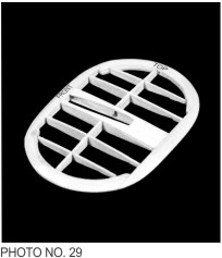
7. Pin and cement part C9 to top of C7 ribs and against the leading and trailing edges. Photo 28.
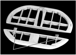
8. IMPORTANT! While still on layout, mark the FRONT and TOP of rudder
|
for identification through out the final assembly of model.
9. Remove frame from layout when dry then cement the other C9 part to the other side of frame, cut off "leveling spurs" on center spar C5.
10. Finally when thoroughly dry, carefully carve and sandpaper the tip parts and leading and trailing edges to a streamlined shape. Except for a final sanding the frame is now ready for tissue covering. Photo 29.
11. Build a second rudder frame in a similar manner over the same layout.
|
|
All stabilizer parts should be checked against the corresponding templates on Section 3 for accuracy of outline, notch locations and size, etc. If any part is oversize, trim to size at this time.
Test fit parts together where joined before starting frame assembly. If any fitting is too tight, widen slightly with a thin knife blade for a smooth fit.
1. The stabilizer frame is easy to build compared with the other frame members. First pin the center spar D1 over the layout. Photo 34.
|
2. Next cut, carve and sand the leading and trailing edges to their streamline shape. Photo 35.
3. Pin leading and trailing edges on top of shims over layout.
4. Finally glue ribs D2 thru D4 to spar D1 and between the leading and trailing edge. Remove frame from layout and add parts D5. Photo 36.
5. Except for a final sanding, the frame is now ready for tissue covering. Photo 37.
|
|
Like the movable rudder project, assembling a stabilizer with movable elevators is an easy task. Modify (cut) eight of the D2 ribs and the two D3 ribs as shown on Section 10. Photo 38.
1. Cut the thin hinge slots in main spar D1 and the 4 elevator spars D8. Now cement the D8 parts together in pairs. Clear hinge slots if clogged with cement or wood.
2. Pin the main/spar (D1) to layout. Pin the "paired" D8 spars to layout, with spacers between spar D1 and the D8 elevator spars.
3. Cut, carve and sand the leading and trailing edges to their streamline shape. Pin them over the shims on the layout. Photo 39.
4. Next pin and glue the ribs and partial ribs between the leading and trailing edges and the spars Photo 40.
|
5. When dry, remove frame from plan & add parts D5A and D7. Cut trailing edge at locations indicated to separate the stabilizer and elevators. Photo 41.
6. Cut four plastic hinges from the clear plastic sheet. Using a thin pointed knife blade, cut through the hinge slots in the spars and into the ribs of the stabilizer and elevators where the hinges will be located in the final model assembly. Test fit the hinges in slots and if they bind, widen slots slightly for a smooth fit. Set hinges and elevator frames aside at this time. Photo 42.
7. Except for a final light sanding, the stabilizer and elevators are ready to be tissue covered. The stabilizer and elevators are only joined after the surfaces have been painted and finished.
|
|
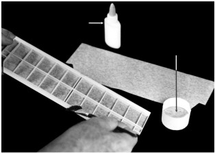
he model can be covered either with the tissue supplied in this kit or with the lightweight iron-on films available at most hobby dealers. Instructions for applying this material is supplied by the manufacturer. The instructions that follow pertain ONLY to a tissue covered model.
Drawing No. 7 shows the frames after being tissue covered. It is important to note that many of the assembly photographs that follow these instructions show the frames without tissue covering. Nonetheless, all frames should be covered as illustrated because it is extremely difficult to apply tissue covering to the framework of an assembled model. A mixture of white glue (such as Elmer's Glue-All) and water is the adhesive recommended to fasten tissue to model frames. Of course model airplane dope, the old standby, can be used for the same purpose but its use is more difficult and less desirable because of its chemical composition. Refer to photos 10 thru 16 and related copy on the General Information Sheet for tips on covering tissue covered model. A 50% glue - water solution makes an excellent tissue adhesive. Because of the stringer, rib and former construction use a narrow ¼” or ½” wide brush to spread the glue mixture.
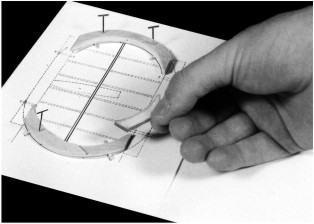
FUSELAGE: Before starting to cover the fuselage, cut out the vacuum formed clear plastic nose and tail turrets (P7 and P8) and test fit them over the nose and tail formers (B1 and B15). If the fit is a bit too snug, sand around the former perimeters until the turrets fit the formers. If too loose,
|
tape thin strips of masking tape to the former perimeters to fill in any gaps.
Cover the fuselage in sections as shown starting from the front or former B1 and covering vertically between formers. The grain of the tissue should run lengthwise with the fuselage. (The grain of the tissue runs with the width of the tissue sheet as you receive it in the kit).
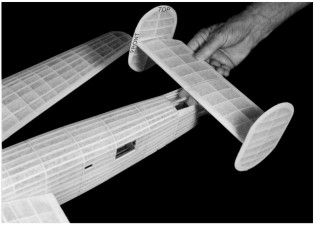
WING: Cover the top and bottom of wing frames in sections shown by line drawings. The grain of tissue must always run spanwise on the wing.
TAIL SURFACES: The rudder can be covered on each side with single pieces of tissue. Tissue grain should run from the base to the tip. The stabilizer is covered in a similar manner - single pieces for both the top and bottom of frames. Photo 43.
After the frames are covered they should be wet with by water by using an atomizer or brush which will cause the tissue to sag temporarily. When a tissue covered frame has thoroughly dried, brush a prime coat of 40% glue and 60% water over all surfaces. This will cause the tissue to sag again but, when dried out, the covering should become taut over the entire framework & be ready for the final color coats at a later stage. Photos 44 & 45.
At this time cut out and prepare the fuselage small window parts (J1 thru J5) as indicated on Plan B. When ready, glue them to their respective openings in the fuselage.
|
|
The tissue covered frames and plastic parts can be painted with water based paints available at a local hobby shop. It is easy to apply, has good coverage and can be cleaned up with plain water - especially for cleaning brushes, spilled drops, etc. Of course, regular model airplane dope can be used for painting purposes but we consider water based colors "safer" and easier to apply and use them in our model development work.
Generally, the colors on the war planes were of a dull finish. Ask for and use a paint that has authentic dull finish. Follow the manufacturer's instructions when using water based paint. Use a good ½" to ¾" brush and proceed as follows: Paint one half of the fuselage at a time starting at the nose (B1) and proceeding to the tail (B15).
Next, paint the top and bottom of one wing panel and stabilizer-elevator and one half of the fin-rudder. When dry, so you can handle the model, paint the remaining half of the model. On the fuselage, brush on all coats the length
|
of the fuselage. On the wing and tail surfaces, brush each alternate coat on in opposite directions, finishing with the last coat running in the same direction as the fuselage. Apply only enough colored paint to give complete coverage - usually two or three coats are sufficient. When more than one color is required, finish the lightest color first and the darker color last, because dark colors cover over light better than light over dark. Allow sufficient time between coats for the paint to dry.
When painting the "ribbing" in the nose, tail and top and bottom gun turrets, you will find it easier to apply the paint on the inside of the part rather than the outside as it is easier to control paint line widths with "inside" painting. After the model parts have been painted add the control surface lines (ruling pen and ink or thin black tape) and decals. Refer to Plan A for the location of these trim items.
|
|
Although some of the photos listed show "uncovered" frames being assembled, all should have been "covered" before assembly is undertaken.
Cut out cardstock parts J13, J14 and, J15. J13 and J15 are glued to formers B1 and B15 respectively. J14, the cockpit interior, is folded to shape and glued to formers B3 and B4 in the cockpit area. (See Plan E, Section 14 for enhancing the interior cockpit detail).
Assuming that the vacuum formed plastic parts
for the fuselage have been cut out, trimmed to shape and "edge sanded", cement
them to the tissue covered fuselage frame starting with the nose cone P8 and
working back to the tail cone P7.
Glue the rudders to the stabilizer then glue the assembled unit to tail of fuselage, Photo 50.
Assemble the main and nose landing gears - see Plan E Section 12 and Photo 51. They can be "lightly" glued into their respective wing and fuselage slots for easy removal (to simulate an in-flight model) or permanently glued in position.
|
Cement the half nacelle shells to the nacelle frames on wing - See Plan E, Sections 9 and 9A. Attach lower half shells first. Any "gaps" appearing where the nacelle shells touch the wing surface should be filled in with plastic balsa filler or similar material. Sand smooth when dry. Refer to Plan "F", Section 13 tor instructions for assembling and installing the four scale propeller units. Take special note that the dummy plastic engines P15 and the propeller hub units (less propeller blades) are assembled before being cemented to nacelle formers G1 and G2.
Cement the four plastic cowls (Pl6) to the nacelles then cement the carved and sanded balsa propeller blades to the plastic hubs.
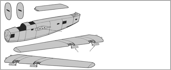
Due to the wing rail structure, the wings can be permanently cemented to the fuselage or merely set in position for removal as desired.
Fit and glue the remaining "P" parts in place aligning carefully according to the scale plans on Plan A. Finally add the simulated wheel wells (J12) to bottom of wings and dummy machine guns.
|
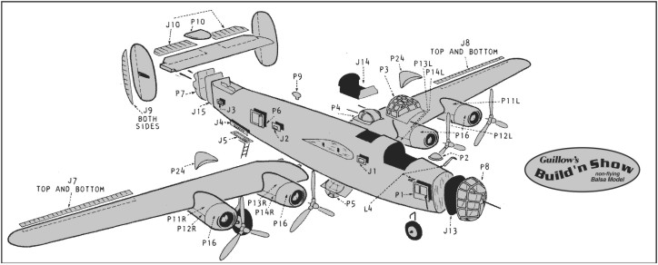
KIT 2003
BUILDING INSTRUCTIONS
CONSOLIDATED B-24D LIBERATOR
Copyright 1990 by Paul K. Guillow, Inc., Wakefield. Mass., U.S.A.
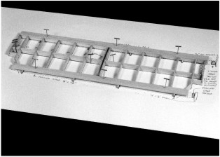
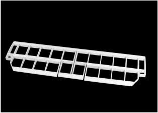
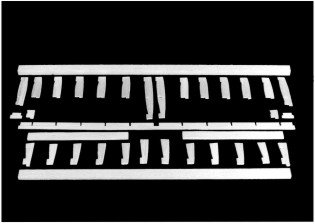
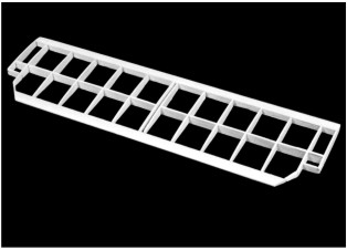
WING RAIL COVERS
|
The wing frame should be tissue covered before attaching nacelles – see special “Covering The Frames” instructions. As with the wing, all nacelle parts should be individually checked against the templates on Sections 9
|
and 9A for size, shape slot thickness, etc. Before starting assemble, cut the four 3/16” x 3/8” balsa rails to length in pairs. Set aside until needed later.
|
|
These parts should only be used on the movable flying surfaces - not on the "fixed" surface frames. See Drawing No.8 for means of simulating the rib
|
impressions visible in actual aircraft. The "J" parts are glued directly to the flying surface frames without any tissue covering.
|
|
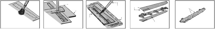
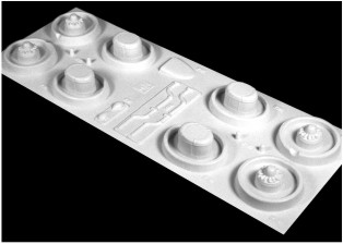
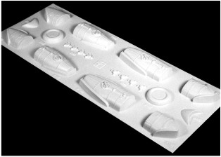
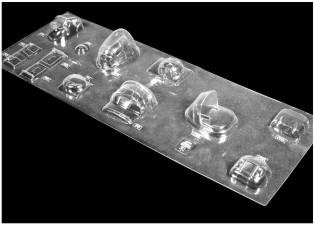
The opaque (non-transparent) plastic parts (sheets No. 1 and 2)( Photos 46 and 47) should each be lightly numbered with a soft lead pencil then cut apart with a pair of scissors (a part number is adjacent to each plastic part). Two pages of the enclosed "Balsa Model Kit Catalog" is devoted to the cutting, cementing and painting of Guillow vacuum formed plastics parts. If not familiar with these techniques, it will pay to read the information supplied before cutting out the parts.
Using the point of a model builders knife or a single edged razor blade, score the plastic part as close as you can at the trim points. The score should be deep but not through. Score twice if necessary. After scoring, gently bend the excess material back and forth until it breaks away. Now
|
sand all the edges smooth. The opaque plastic parts are now ready to be attached to the model. The opaque plastic parts Sheet No.3, Photo 48 are made of acetate that is a different material than used for the opaque plastic parts. Extra special care should be taken when cementing clear plastic parts in place and when painting in the window separations since a smear of cement over a window will mar its clarity. Use plastic cement when joining the matching halves of parts that require joining before being added to model. After cement has dried, lightly sand the joints for a smooth finish.
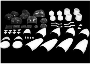
Photo 49 shows all plastic parts cut to shape and ready for such painting as needed.
|
NOTE: Leading and trailing edges shown above to be “shaped” after frame assembly.
NOTE: Leading and trailing edges shown above to be “shaped” after frame assembly.