


KIT 2002 BOEING B-17G FLYING FORTRESS
BUILDING INSTRUCTIONS
|
Experienced model builders will find this B-17G kit to be quite similar in most respects to that of a typical Guillow model airplane kit. However, there are enough differences to warrant a careful study of plans and instructions before starting construction. Failure to do so will risk errors that will be difficult to correct once made.
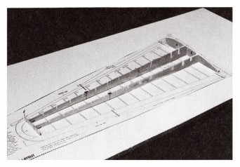
If you are a beginner, a reading of the small 24 page booklet enclosed titled "How To Build and Fly A Balsa Model Airplane" will provide helpful basic information about the subject. In some areas you will find that the B-17G construction and assembly differs from that described in the booklet. In these instances always follow the B-17G instructions. One of the major differences of this B-17G kit from other Guillow kits is the treatment of the plans that are divided into "reference" and "cut apart" sheets. The former are for reading only - the latter are "work sheets" on which the model frames are built after they have been cut into smaller sections. In addition to ease of handling, these cut-apart plan sections provide full size templates of the
frame parts
|
second important difference is the preparation of the die-cut balsa wood parts before starting frame construction. This is especially so of the fuselage formers and wing ribs that require 'notching' for the 3/32" sq. stringers and spars. The step-by-step instructions that follow describe the assembly of a non-flying exhibition model without movable flying surfaces. If you wish to build your model with movable flying surfaces, read the information on Sections 8, 9, 10 and 11,1 of Plan "E". If you intend to build a U/Control model, see section 21 of Plan "D" and the top portion of Plan "A" for the parts modification and additions needed to create such a model. Complete step-by-step U/Control model instructions are provided elsewhere. Only those with some knowledge of U/Control model building and flying should attempt to build the B-17G as a U/Control model since such a project is not recommended for beginners.
|
BUILDING MATERIAL AND TOOL REQUIREMENTS
|
There are a number of model building tools and accessories needed that are not supplied in the kit. These should be accumulated before starting model construction. Many are available at home - others must be purchased at a local hobby shop. See page 2 of the booklet "How To Build and Fly a Balsa Model Airplane". Other additional tools and materials required are as follows: WORKBOARD. Minimum size: 10"x33". A 24"x48" foam plastic ceiling panel makes an ideal workboard. (See special offer enclosed for a professional model builders all balsa workboard of lasting value). ADHESIVE. Instant Glue - can be used in place of balsa model cement for assembling all of the parts of a non-flying model except for
|
coating the nylon landing gear bindings. Do not use if building a U/Control model. PLASTIC BALSA FILLET MATERIAL. For filling in gaps in joints. SARAN WRAP. An excellent substitute for wax paper. WIRE CUTTERS. For cutting wire parts. NEEDLE NOSE PLIERS. Two pair for bending wire parts. WOOD PLANE. Small model builder type. HAND SAW. Fine tooth, single edge model builder type. TRIANGLE (or SQUARE BLOCKS). Small size for former alignments. HAND DRILL and BITS. For drilling holes in vinyl, etc. FLAT ENAMEL and ENAMEL THINNER. For finishing color coats.
|
PRE-WORK INFORMATION
|
The instructions that follow cover ,the building of the fuselage, wing, rudder and stabilizer frames in that order. If desired, the rotation can be changed if you wish to build the smaller and simpler rudder and stabilizer frames first. This is easy to do with the new Guillow reference and work sheet arrangements. At the start, a decision should be made to build the model either with the standard tail gun arrangement shown on Plans "A" and "B" or with a Cheyenne tail (shown in Section 19, Plan "G'') as installed in the late B-17G production models. The latter section shows the parts modifications necessary to make this change. Plan "G' 'also shows other optional features that can be considered if you wish to incorporate them in your model.
|
If using balsa wood cement for joining balsa wood parts, it is recommended that a thin coat of cement be smeared on all contacting surfaces before frame assembly for an extra strong bond. This does not apply to instant glue. Although most of the shaped balsa parts are die-cut, several of the small parts are only printed on the die-cut sheets and must be cut out with a model builders knife or single edge razor blade. This is done to prevent the crushing that often occurs when very small parts are die-cut.
To avoid misplacement or loss of die-cut balsa parts, it is strongly recommended that only the parts for a specific model frame be removed from the die-cut sheets at one time.
|
PREPARATION OF DIE-CUT FUSELAGE FORMERS
|
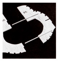
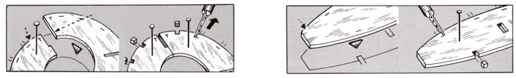
First cut out Section 6 of Plan "D" with the printed fuselage former templates and pin to the workboard with thumb tacks. Next carefully remove all formers (B1 thru B16) from die-cut balsa sheets cutting them loose with the point of a model builders knife if necessary. Lay each former half over its respective template then, with a soft pencil, lightly mark the former number on the face of any half former whose printed number is concealed on the bottom surface.
Note that the half B14 formers are die-cut in three sections and that these sections MUST be temporarily connected with short pieces of 1/16" sq. strip stock before being removed from the die-cut balsa sheet - see special note on the sheet stock. These pieces of strip stock and the center sections of the joined B14 halves are removed later when the stabilizer is attached to the fuselage. The 3/32" sq. stringer notches in the half formers are only partially die-cut and, to clear them, the sides of the notches must be cut with the point of a razor blade or model builders knife. Pin each right and left half former over its respective template then finish the stringer notches as shown in Drawing No. 1 on page 8. All former halves are die-cut with 1/16" deep shoulders to match the 1/16" thickness of the center keel parts (A1 thru A5). All former halves that are to be cemented to the pinned down center keel (for left side of fuselage) are to be used with the 1/16" shoulders
|
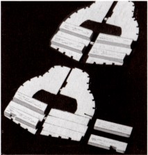
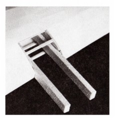
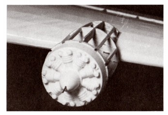
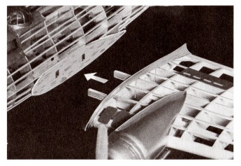
as die-cut. All of the matching former halves (for right side of fuselage) MUST have these 1/16" shoulders trimmed off so that when they are cemented in place, they will fit flush against the center keel and left side formers. Use a straight edge and razor blade to carefully remove these 1/16" shoulders. Photo 1. To achieve a positive alignment of the fuselage half formers when they are cemented to the center keel, the following optional method is suggested. Cut and lightly cement two pieces of 1/16" sq. balsa strip to each of the half formers without the shoulders as per templates. Do not cement to the former halves with the shoulders. Photo 2. These strips will provide an exact "in line" alignment when the "shoulder less" half formers are cemented to the center keel and the first set of half formers. Once the fuselage frame has been completed, the alignment sticks can be "popped off" if not permanently cemented in place before hand to reinforce the formers.
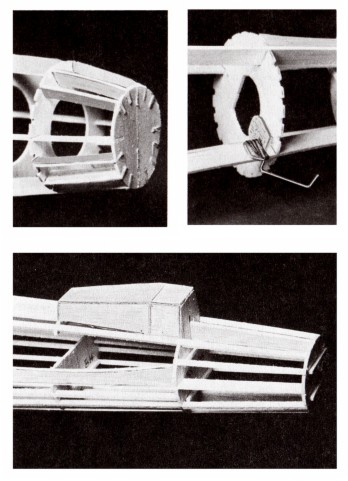
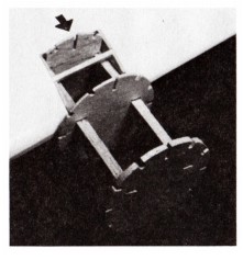
There are eight 3/16"x 3/8" blocks that support the wing rails when the latter are inserted into the fuselage. They must be cut to length and cemented to the FRONT of half formers B6 and B7 at this time. Position them precisely on the former halves using a spare piece of 3/16"x 3/8" stock as a spacer between the two blocks. Do not make the fit so tight that the spacer will not slide easily between the blocks. Photo 3.
|
FUSELAGE CONSTRUCTION
|
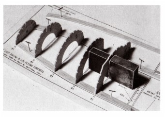
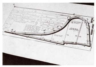
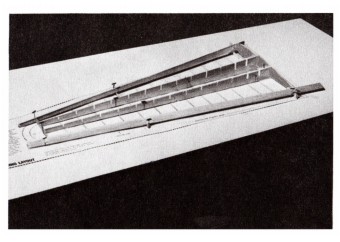
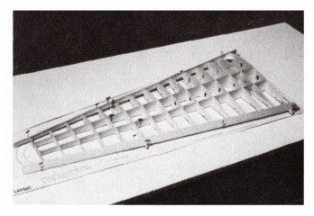
1. Cut out the Fuselage Layout (Section 1, Plan "C"). Lay on workboard then cover with Saran Wrap or wax paper fastening both in place with thumbtacks. Remove center keel parts Al, A2, A3, A4 and A5 from die-cut balsa sheets and pin and cement them together over Fuselage Layout. Photo 4.
2. Cement two A4A former spacers onto the A1 and A4 keel parts. These spacers set the positions of half formers B6 and B7 that in turn align them exactly with the wing frame rails that slide into the fuselage during model assembly.
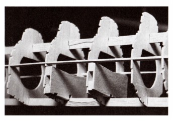
3. Starting with B1, cement all of the left side half formers to the center keel "squaring" them up with a small triangle (or square blocks) so that they are exactly at right angles (90") to the center keel. They must be supported in this position until the cement has dried hard. Photo 5. At this time, mark the positions of half formers B8A and B11A on the center keel parts.
|
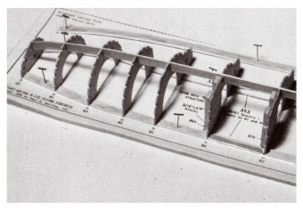
4. Next pin and cement one set of side keel parts A6 and A7 over the Side Keel Layout. (Shown in Photo 4). When dry, remove from layout then join the second set of A6/A7 parts over the layout in a similar manner.
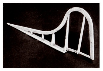
5. Cement one of the completed side keels into the deep notches in half formers B1 thru B16 after it has been scored on the bottom, cracked and bent slightly upward at former B10 as shown in the fuselage drawing on Plan "B". Photo 6.
6. Carefully remove the frame structure from fuselage layout. Cement the remaining half formers to the center keel and first set of half formers. Photo 7.
7. Cement the second side keel to the second set of half formers.
8. Cement "covers" B6A and B7A over the 3/16"x3/8" blocks on formers B6 and B7 Photo 8.
|
|
9. Slip partial formers B8A and B11A into position on the keels, line up Carefully then cement in place.
10. Fit and cement wing roots parts L1 and stabilizer supports L2 to both sides of the fuselage frame. Photos 9A and 9B.
11. Cement nose shaping pieces A8, A9, A10 and A11 to and between formers B1 and B2. Photo 10.
12. Cut and bend the tail wheel wire to shape then cement it to center keel part A5 -see Section 16, Plan "F". When dry, cement vinyl piece K1 to the wire and formers B13. Next bind the wire and keel with nylon thread. Coat the entire unit with a generous coat of cement. Photo 11. If a retractable tail wheel is desired, see Section 17, Plan "G".
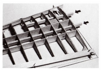
13. The next job is to fit and cement the 3/32" sq. balsa stringers into the notches in the formers. It is best to install stringers in matching pairs - one on the left side and then its opposite on the right side. This will prevent any frame distortion that might result if all or most of the stringers on one side
|
were installed before adding those to the other side. See full size top and side view plans of fuselage frame on Plan "B" for stringer locations. Photos 12A and 12B. Before adding the three top center stringers between formers B5 and B8, cement small top former B8B in position.
14. Cement small former B15A on top of center keel and stringers. When dry, cement parts L3 and L4 to the top of formers B14, B15A and B15 then fit and cement parts L5 and L6 on each side of frame. Photo 13. Finally, remove the center section of former B14 that was tack cemented to the top and bottom B14 parts so that the stabilizer can be attached to the fuselage when the model is being assembled -shown in Photo 13.
15. Remove the "Q" planking sections from balsa sheet stock and cement them between the formers and stringers as shown on fuselage frame drawing. (Plan B) The fuselage frame can now be set aside until it is to be readied for tissue covering and addition of the plastic parts such as cowl, tail cone, gun turrets, etc.
|
WING CONSTRUCTION
|
The right and left wing panels are similar and can be assembled individually or both at the same time if desired. The instructions that follow describe the
|
left wing frame assembly (Plan "B") but are equally valid for the right wing.
|
PRE-ASSEMBLY WORK AND INFORMATION
|
All wing parts should be checked against the corresponding templates on Section 7, Plan "D" and the right and left wing layouts (Sections 4 and 5, Plan "C") for accuracy of outline, notch locations, size, etc.
As with the fuselage formers, the 3/32" sq. spar notches in the ribs are only partially die cut and, to clear them, the sides of the notches must be cut with the point of a razor blade or model builders knife. Pin each rib or sub-rib over its respective template then finish the spar notches as shown in Drawing No. 2.
The long notches in the ribs that mate with those in the main spars (MS1 and MS2 parts) should permit these parts to slide together without undue force that might cause breakage. Test fit the parts together before starting frame assembly and, if any notch is too tight, widen slightly with a razor blade. Aim for a smooth fit, not a loose mate.
The leading edge (1/4"x 5/8"x 22" stick) should be tapered and rounded as shown and described in Section 7, Plan "D". The pre-cut trailing edge will need a slight tapering from the root rib (F1) to wing tip to precisely fit the tail
|
ends of the ribs (from 1/4" at rib F1 to 3/16" at rib F15).
This can be done either before or after it is cemented to ribs.
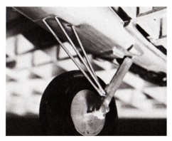
It is recommended that the nose and tail ends of ribs be given a slight taper with sandpaper to conform to the slant of the leading and trailing edges as shown in Drawing No. 3. Do not shorten ribs when sanding - a slight taper is sufficient. You have the choice of installing the extended main landing gear as shown on Plan "A" or a dummy retracted gear (plastic part No. P35) which is cemented directly to the bottom of the inboard nacelle as part of the final model assembly. For extended gear, assemble it as shown in Section 12, Plan "F". A small clamp, rubber band or clothes pin will be found useful to hold the parts securely together when drying. When dry, bind parts tightly with the nylon thread then coat binding liberally with cement. Enlarge the axle holes in the plastic half wheels with a 3/32" bit. Next cement two wheel core parts LG2 together then, when dry, cement them between a pair of plastic wheel halves. When dry, sand the LG2 core flush with plastic wheel halves. Finally, assemble gear, wheel and small plastic lockwashers.
|
BUILDING THE LEFT WING FRAME
|
It is extremely important that the step-by-step instructions that follow be fully understood before starting assembly. Failure to follow the steps outlined may result in an inability to add an important part to the frame after an out-of sequence construction step has been taken. If you wish to build wing frames with movable ailerons, see separate instructions supplied before starting construction.
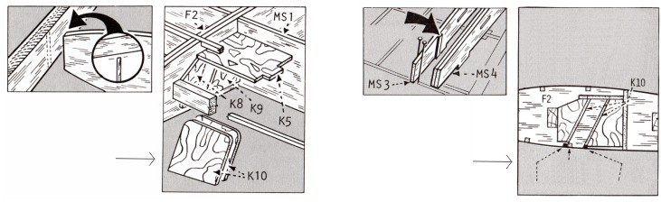
1. Pin and cement the main spar halves (MS1-A/MS1-B and MS2-A/MS2-B) together over their layouts on Section 5. Be sure the bottom edges are in a straight line and that the notches in the die-cut balsa parts exactly match those on the drawings. This latter matching Is very important since it determines the rib alignments when the ribs are cemented to the spars. Any slight variations in notch alignments should be corrected at this time.
2. Next cement ribs F2 and F3 together in matching pairs. When dry, cement vinyl parts K6, K7, K8 and K9 to the "doubled up" F2 and F3 ribs making SURE that they are cemented to the proper sides of the ribs as shown on the wing plan (Plan "B"). A precise placement of these vinyl parts is critical since it determines the angle of the landing gear when it is installed in the wing.
3. Cement parts F6A/F6B and F7A/F7B to ribs F6 and F7 aligning them accurately as per their templates on plan. Next cement parts F2B/F2C and F3B/F3C to sub-ribs F2A and F3A. Be SURE all of the above parts are cemented to the proper sides of F6, F7, F2A and F3A as per plan since it will be very difficult to reposition them once the frame is in the process of being assembled.
4. Pin Left Wing Layout (Section 4) to the workboard. Special Note - if building model with movable ailerons, cut out the movable aileron drawings (see Sections 9, 10 and 11) and tape or cement them to the left and right wing layouts and wing plan. Also read the "Installing Movable Aileron" instructions that follow these wing construction directions.
5. Cover Left Wing Layout with Saran Wrap or similar material. Pin the main spars (MS1/MS2 parts) over layout making SURE they are at right angles to the layout surface. Slide ribs F1 and F15 into position on main spars lining them up carefully and making sure the bottom of the ribs between the main spars rest flat on the layout. Cement in place. Photo 14.
6. Position and pin the leading and trailing edges against ribs F1 and F15 first blocking them up to the proper height with die-cut alignment gauges W, X, Y and Z. The nose and tail ends of the ribs should now line up with the flat edges of the leading and trailing edges. If there is more than a slight variance, raise or lower the leading and trailing edges slightly until they match with the rib ends. Once the proper positioning has been achieved, cement and pin the leading and trailing edges to the F1 and F15 rib ends. Photo 15.
7. Now press the two double ribs F2 and F3 onto the extensions of vinyl part K5 and then press them both at the same time into position On the main spars and between the leading and trailing edges. Photo 16. If needed, lower or raise the rib ends slightly to match the leading and trailing edges. Once the proper alignment is achieved, lift ribs partially from main spar notches, coat contacting areas with cement (except as noted below) then press ribs back into position. Note - either lightly or omit cementing the nose of double F3 ribs to the leading edge since a portion of the leading edge must be cut away later when attaching the nacelles to the wing frame.
8. Now proceed to fit, align and cement ribs F4 thru F14 to the main
|
spars and leading and trailing edges making sure the rib ends and the leading edges and trailing edges line up correctly. The triangular corner brackets E1 and E2 can be cemented against the F1 rib and the leading and trailing edges. Photo 17.
9. Cut the two 3/16"x3/8" rail spars to length, (see Section 20, Plan "G") then "thread" them thru the rectangular holes in ribs F1 thru F7. Cement in place. Photo 18.
10. Remove the partially completed wing frame from the layout and lay it down bottom side up. Fit and cement the two K10 vinyl parts between and against the K5, K6, K7, K8 and K9 parts previously cemented to double ribs F2 and F3. This will form a slot or cell in the bottom of wing into which the previously assembled main landing gear unit fits when the model is in the final assembly stage. See Drawing No. 4. Test fit the gear unit into the "cell" before the cement holding the K10 parts dries hard. If a bit tight, remove one of the K10's and sand down the thickness sufficiently to ease the fit. If loose, any gap can be filled in with balsa filler material when the gear is installed. As designed, the gear can be permanently fastened to the wing or, if desired, be omitted and replaced by the plastic dummy retracted gear provided in kit to simulate in-flight appearance.
11. Fit and cement wing tip parts E3 to the leading and trailing edges and to where it contacts rib F15. Center it between the leading and trailing edges before the cement hardens then set frame aside until the cement bond is firm.
12. The next step is to add sub-ribs F2A and F3A to the frame. Using the two die-cut Rib Spacing Gauges as spacers, position the F2A and F3A sub-ribs on each side of double rib F3 and against the front rail spar. Photo 19. Line up carefully and accurately then cement in position cementing very lightly where the sub-ribs contact the leading edge. This alignment is very important because it effects the alignment of the inboard nacelle when it is being attached to the wing frame.
13. The last attachment to the wing frame is the 3/32" sq. spars. These are added one at a time and can be "dry fit" first to check the notch widths and depth. If, when sighting along a "dry" positioned spar, a small waver in alignment is noted, this can be corrected by slightly widening the notch that causes the misalignment. Also, if a notch does not permit a spar to fit down flush with the top or bottom of a rib, the notch can be cut slightly deeper with a pointed modeler's knife. Photo 20.
14. The excess leading and trailing edge lengths can now be cut off at one end to form the finished wing tip and at the other end flush with the face of rib F1.
15. By carving and sanding, blend in the leading and trailing edges from rib F15 to the contact areas on E3. Also sand the 3/32" sq. spars from rib F15 to blend into the tip. Trim off the "leveling spurs" on bottom of ribs and sand smooth.
16. Turn frame bottom side up and remove the portion of the bottom spar between ribs F2 and F3 as illustrated in Drawing No. 6. Replace with the 1/16" sq. strips shown in drawing. Also see wing plan for the removal of a portion of the forward bottom spar between sub-ribs F6B and F7B.
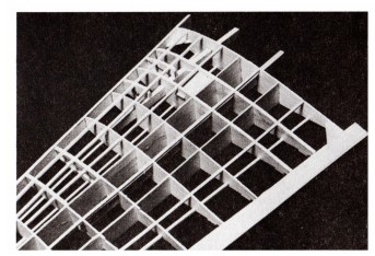
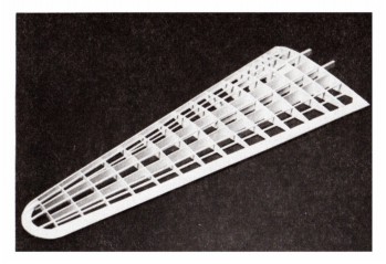
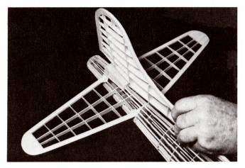
At this stage, except for a final sanding, the left wing frame is complete and ready for the addition of the inboard and outboard nacelle structures. Photo 21. The right wing frame can now be constructed in a similar manner.
|
DETAILS OF CONSTRUCTION, TISSUE COVERING AND ASSEMBLY
Dry covering scheme shown. If wet covering used, larger sections can be covered at one time without creating unsightly wrinkles.
DRAWING NO. 8 Treating the "J" cardstock parts for moveable flying surfaces.
DRAWING NO. 9 Assembling the model.
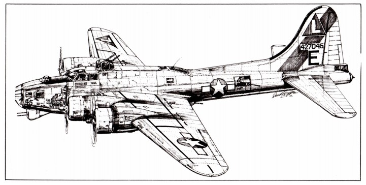
B-17G Flying Fortress - courtesy of Mr. David G. Diggins, Lancaster, England.
OPTIONAL
J18, J19 AND J20 PARTS MAY BE USED INSTEAD OF OUTLINING AREAS IN BLACK STRIPING
|
The wing frame should be tissue covered before attaching nacelles - see special "Covering The Frames" instructions.
As with the wing, all nacelle parts should be individually checked against the templates on Sections 13 and 14 for size, shape; slot thickness, etc. Before staring assembly, cut the four 3/16" x 3/8" balsa rails to length in pairs and accurately mark on them the positions of formers G2, G3/G4/G5 and G6/GT. Set aside until needed later.
The two inboard nacelles have dummy wheel well openings and
|
require two of the four G2 formers to be slightly modified as per the G2 template - do this and set to one side.
All of the OB and IB nacelle parts are die-cut for full length nacelles. If installing a gas engine for U/Control flying, the OB parts for the outboard nacelle must be shortened as per the templates on Section 21, Plan "D". Also, for gas engine mounting, hardwood rails are supplied that are to be used in place of the balsa ones. Mark the G2 and G6/G7 former positions on the hard rails.
|
PRE-ASSEMBLY WORK AND INFORMATION
NACELLE CONSTRUCTION
|
1. Carefully
cut away the portions of leading edge between ribs F2A and F3A and between ribs.
F6 and F7 as indicated on plan and Sections 13 and 14. Save the cutaway
sections because they are cemented back in place as a later step. The use of a
thin blade model builder's saw is recommended for cutting thru the thick leading
edges. Photo 22.
2. Cement
the previously prepared nacelle rails to the ribs and against the wing rail
spars. Before cementing the rails permanently in place it is suggested that
formers G1 and G2 be "dry" positioned on the rails to insure precise spacing.
When cementing the rails in position, apply cement generously to create a strong
bond between the nacelle rails and wing parts. Photo 23. Let cement dry hard
then line formers G1 and G2 and cement them in place. Photo 24.
3. Cut the two sections of the "saved"
leading edge to length to fit
|
between the rails -cement in place. (If desired,
unshaped pieces of 3/16" x 3/8" stock can be substituted since they will be
hidden when the plastic nacelle covers are added). 3A. If installing a gas
engine (outboard nacelle only) cement the vinyl motor mount (firewall) K11 to
the face of G1 former first boring the four engine bolt holes in K11 as
indicated by the punch marks in the vinyl. Next cut out the cement and 1/16"
triangular supporting braces to the back of G1 and against the hard wood rails.
4. Cement
formers G3, G4, G5, G6 and G7 in place aligning them carefully before the cement
dries hard. Photo 25.
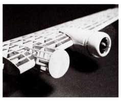
5. Finally
cement the OB and IB parts to the formers and cut and attach the 3/32" sq.
stringers. Photo 26. (This picture also shows how the main landing gear is
installed in the bottom of wing). Add right wing nacelle frames in a similar
manner.
|
INSTALLING MOVEABLE AILERONS
See Sections 10 and 11 on Plan "E"
|
To build movable ailerons as part of the wing structure, the following steps must be taken during frame assembly as outlined below. Following Step 1, 2, 3 and 4 of the left wing frame assembly instructions, select die-cut spar MS3 and cut the two hinge slots in it as shown on template. When finished, pin MS3 over its location on the frame layout with "leveling tabs" touching layout and the thin end towards wing tip.
Next trim die-cut ribs F10, F11, F12, F13 and F14 to the lengths shown on templates then cut the aileron ribs F9A, F10A, F11A, F12A, F13A, F14A and F15A from printed balsa sheet, Set both sets of ribs aside at this time. Now turn to and complete steps 5 thru 7.
Before proceeding to step 8 select two of the MS4 spars and, after cutting the two hinge slots in each, cement them together to form a double spar. Make two 1/32" thick spacers from wood or cardboard (Drawing No. 5) and lightly cement them to the trailing edge face of MS3 as shown. Now, setting the MS4 in position on layout, lightly cement it to the two spacers pinning in position until dry. Do not cement MS4 to MS3!
Now proceed to steps 8 and 9 and, when completed, remove the partially completed frame from the layout. Cement E4 pieces on each side of wing tip.
Using a thin saw blade, carefully cut away the portion of the trailing
|
edge between ribs F9 and F15 then re-pin the wing frame in position over the layout.
Two pieces of 1/8" x 1/4" x 8 3/8" stock are provided for the movable aileron trailing edges. Both should be tapered to conform to the main trailing edges - see sectional drawings on Section 10. After tapering, pin one in place over the layout blocking it up to the height of the main trailing edge and securing in place with lightly cemented temporary 1/16" sq. connectors as shown. Now cement the aileron ribs (F9A thru F15A) between the MS4 spar and trailing edge.
When dry, remove the 1/16" sq. connectors then cut thru the spacers holding the MS3 and MS4 spars together to free the aileron frame from the main structure -cut or sand away any remaining portions of the spacers on MS3 - MS4.
Carve and sand the front of the MS4 spar to the rounded shape shown by the aileron sections. Cut the plastic hinges from clear plastic sheet. Clear the hinge slots in MS3 and MS4 and, thru them, make thin incisions in ribs F10, F10A, F14 and F14A to take the hinges. "Dry fit" hinges in the MS3 and MS4 hinge slots and, once properly fitted, set hinges and aileron frame aside until later.
Now refer back to steps 10 thru 15 for completion of the wing frame.
|
RUDDER CONSTRUCTION
See Plan "B" and Section 2, Plan "C"
|
All rudder parts should be checked against the corresponding templates on Section 2, Plan "C" :or accuracy of outline, notch locations and size, etc. If any part is oversize, trim to size at this time.
The long notches in the ribs that mate with those in the main spars should permit these parts to slide together without undue force that might cause breakage. Test fit the parts together before starting frame assembly and, if any notches are too tight, widen slightly with a razor blade.
The rudder is built partially over the Rudder Layout (Section 2) then, when dry, is removed for final assembly off the work board.
1. First pin and cement together the die-cut outline parts C1, C2, C3 and C4 over rudder layout. Pins should be placed along the edges of parts not thru them since a second layer of parts is to be assembled over the first as the next step.
2. Next pin and cement together and to C1, C2, C3 and C4 the outline parts C5, C6, C7 and C8. Pin thru the double layer of parts to hold them securely in place. Place a few small weights on top of the parts at random to strengthen the bond between the two layers of parts - let dry hard. Photo 27.
3. Cut shims from 1/16" sq. strip stock and place on layout where indicated. Pin in place if necessary.
|
4. Cement parts C9 and C10 together (over but not to shims) and against the rudder Outline parts. Photo 28.
5. When dry, remove the partially completed frame from the layout and cement parts C17, C18 and C19 to the bottom surfaces of C9 and C10.
6. Cement parts C15 and C16 together carefully lining up the rib slots so they match exactly.
7. Next, accurately position and cement vertical uprights C11, C12, C13, C14 and the double upright C15/C16 between the outline parts. It is important that the ends touching the outline parts be tapered to fit snugly against these parts - this is especially true of C11, C12 and C15/C16. Tapering can be accomplished with a razor blade or sandpaper. Taper only - do not shorten parts! Photo 29.
8. When dry, cement ribs C20 thru C25 to vertical uprights and against the outline parts. Here again, the rib ends should be accurately tapered for flush fittings. Photo 30.
9. Cement part C26 between C20 and outline parts.
10. Finally, when thoroughly dry, carefully carve and sandpaper the double layered outline parts to a streamlined shape - this also includes the excess material at the front of C17. The frame is now ready for tissue covering.
|
|
Assemble the partial frame exactly as described for a non-movable rudder - steps 1 thru 5.
1. Next, widen the slots in ribs C20 and C25 as shown on the templates.
2. Cut C19 to its new C19A length before cementing to the bottom of C10. Also cut the 1/32" wide hinge slots in vertical uprights C15 and C16A.
3. Cement the two 3/32" thick C16A parts together carefully lining up the rib slots so that they exactly match. Check hinge slots for clearance after cement dries. Re-cut slots if clogged up.
4. Position and cement the vertical uprights C11, C12, C13, C14, and C15 between the outline parts.
5. Cement two 1/32" thick spacers (wood or thin cardboard) against the back face of C15 - see layout- then cement the double C16A to C10/C19A
|
and against the spacers but not against C15.
6. Cement ribs C20 and C25 to vertical uprights and against the outline parts. Do NOT force tight joints - widen slightly if needed for a smooth fit.
7. Cement the two C27 parts together and in position on top of rib C20 - also add C26 at this time.
8. When all joints are dry, carve and sand the double layered outline parts to a streamlined shape.
9. Now cut through the outline parts to start to free the rudder from the fin - see plan. A pointed knife blade will do the trick.
10. Next, using a thin saw blade, carefully cut the rudder structure free of the fin.
|
ATTACHING NACELLE FRAMES TO LEFT WING FRAME
See Sections 13 and 14 on Plan "F"
BUILDING FRAME WITH MOVEABLE RUDDER
See Sections 8 and 11 on Plan "E"
|
When separated, sand any protruding rib ends flush with the C15 and C16A surfaces.
11. Now carve and sand the front edge of the C16A part and C27 to the rounded shape shown on the plan.
12. Cut the two plastic hinges from the clear plastic sheet. Using a thin pointed knife blade, cut thru the hinge slots and into the ribs where the hinges will be located. Test fit hinges at this time. If needed, clear
|
hinge slots for a firm smooth fit.
13. Fill in the small area at the top of C15 that forms a part of the fin/rudder gap with scrap balsa.
14. Except for a final light sanding, the fin/rudder frames are ready to be tissue covered at a later model building stage. The fin/rudder are only joined with the plastic hinges after the surfaces have been painted and finished.
|
|
All stabilizer parts should be checked against the corresponding templates on Section 3 for accuracy of outline, notch locations and size, etc. If any part is oversize, trim to size at this time.
Test fit parts together where joined before starting frame assembly. If any fitting is too tight, widen slightly with a thin knife blade for a smooth fit. The leading and trailing edges are supplied as individual pieces of strip stock that are cut into three separate segments shown on Section 3. The two leading edge right and left panel parts should be tapered with a small modelers plane before attaching to the ribs with the final nose shaping being done after the frame has been assembled. Cut the trailing edge stock in the three pieces shown then set both the leading and trailing edge parts aside until needed.
It is recommended that the nose and tail ends of ribs be given a slight taper with sandpaper to conform to the slant of the leading and trailing edges. Do not shorten ribs when sanding - a slight taper is sufficient.
1. Pin spars Dl, D2 and D3 to layout strongly cementing the D2's and D1 together. The "leveling spurs" on the D2 and D3 parts should rest flat on the layout so that the spars maintain their proper level. Photo 31.
2. Accurately cut the shim blocks used to block up the leading and
|
trailing edges and pin to layout where indicated.
3. Pin and cement the leading and trailing edge parts together over the layout. Pre-cement the joints before final cementing for a good bond. Photo 32.
4. Cement ribs D4 thru D10 to the Dl, D2 and D3 spars lining them up to mate with the leading and trailing edges. Photo 33.
5. Next cement the D11 tips between the leading and trailing edges. When dry, remove frame from layout and add the 1/16" sq. strips that are cemented to both sides of Dl 1.
6. Cut eight corner fillets from printed balsa sheet stock and cement them in position in frame.
7. Next to last, shape the leading and trailing edges to their streamlined shape with a model builders knife and sandpaper. If any rib end is not flush with the top and bottom of the leading and trailing edges it should be sanded to smoothly blend in with these parts. Trim the overhanging leading and trailing edges to blend in with D11 tip parts. Photo 34.
8. Finally, sand the leading and trailing edges and the 1/16" sq.'s from ribs D10 so as to blend in with tips D11.
|
ASSEMBLING FRAME WITH MOVEABLE AILERONS
See Sections 9 and 11 on Plan "E"
|
1. Modify ribs D5 thru D9 as shown by templates on Section 9. Number the cut off rib sections D5A thru D9A , etc. that will become part of the elevator. Set aside for later use.
2. Cut the thin hinge slots in main spar D3 and the four elevator spars D12. Now cement the D12 parts together in pairs. Clear hinge slots if clogged with cement or wood.
3. Pin spars D1, D2 and D3 to layout strongly cementing the D2's and D1 together.
4. Cut the shim blocks required to block up the leading and trailing edges over layout - pin in place.
5. Pin and cement the leading and trailing edge sections together over the shims on the layout (but not to shims).
6. Cement full ribs D4, the nose sections of ribs D5 thru D9 and full ribs D10 in place.
7. Next cement the D11 tips between the leading and trailing edges.
8. Cut and lightly cement 1/32" thick wood or cardboard spacers against the D3 spar then pin (but do not cement) the double D12's to layout snug against spacers.
|
9. Cement the short rib ends between the D12's and trailing edge - also add short rib D4B between D3 and trailing edge.
10. When dry, remove the frame from the layout and carve and sand the leading and trailing edges to their streamlined shapes.
11. Cement 1/16" sq. strips to both sides of the D11 's then sand them so they blend in with the leading and trailing edges.
12. When dry, cut thru the trailing edge to free the elevators from the stabilizer.
13. Now carve and sand the final round shape of the D12 elevator spars - see typical elevator section drawing.
14. Cut four plastic hinges from the clear plastic sheet. Using a thin pointed knife blade, cut thru the hinge slots in the spars and into the ribs of the stabilizer and elevators where the hinges will be located in the final model assembly. Test fit the hinges in slots and if they bind, widen slots slightly for a firm smooth fit. Set hinges and elevator frames aside at this time.
15. Except for a final light sanding, the stabilizer and elevators are ready to be tissue covered at a later model building stage. The stabilizer and elevators are only joined after the surfaces have been painted and finished.
|
|
The model can be covered either with the tissue supplied in this kit or with the new lightweight iron-on films available at most hobby dealers. No pre-doping or painting is required when iron-on films are used. Instructions for applying this material is supplied by the manufacturer. The instructions that follow pertain ONLY to a tissue covered model.
Drawing No. 7 shows the frames after being tissue covered. It is important to note that many of the assembly photographs that follow these instructions show the frames without tissue covering. Nonetheless, all frames should be covered as illustrated because it is extremely difficult to apply tissue covering to the framework of an assembled model.
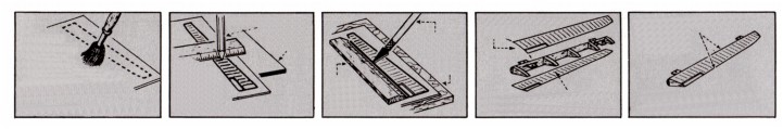
After all the frames have been sanded smooth, they must be pre-doped so that when you apply the tissue covering, the dope used to adhere the tissue to the frames will not be soaked up by the wood. This makes it much easier and faster to cover the model.
Because of the stringer and former construction, use a narrow 1/4" or 1/2" wide brush to dope with. Use dope thinned out 50% with thinner to about the consistency of milk so it will brush easy and dry fast.
The outside surface of all stringers, formers, ribs, leading edges, trailing edges, spars and tips should be given at least three coats of clear dope at which time you will note that the doped surfaces will begin to shine a little. This shows that you have sufficient build-up of dope on the wood. Lightly sand wood between coats of dope. There are two methods of covering a model with tissue. One is to cover with the tissue dry and the other is to cover with the tissue wet. When covering with dry tissue, smaller areas are covered at one time. Any area that is covered dry should be tried first to make sure it will not bunch up or wrinkle excessively before doping in place. The covering scheme shown is suggestive of dry covering. For dry covering, cut the tissue slightly larger then the area to be covered and after doping in place, trim excess tissue with a single edge razor blade.
Dry Covering The Frames
FUSELAGE: Before starting to cover the fuselage, cut out the vacuum formed clear plastic nose cone (P13) and test fit it over former B1. If the fit is a bit too snug, sand around the former perimeter until the cone slips in place. Now set the nose cone aside until later.
|
Cover the fuselage in sections as shown starting from the front or former B1 and covering vertically between formers. The grain of the tissue should run lengthwise with the fuselage. (The grain Of the tissue runs with the width of the tissue sheet as you receive it in the kit)
Wing: Cover the top and bottom of wing frames in sections shown by line drawings. The grain of tissue must always run spanwise on the wing.
Tail Surfaces: The rudder can be covered on each side with single pieces of tissue. Tissue grain should run from the base to tip. The stabilizer is covered in 10 sections as per line drawing - 5 pieces on the top - 5 pieces on the bottom. Tissue grain should run spanwise.
After the frames are covered, they should be wet with water by using an atomizer or by using some of the tissue folded several times and used like a brush to lay the water onto the tissue. When the water has evaporated and the tissue has dried, the tissue will be taut. At this time, brush on one coat of dope over all of the covered parts.
Wet Covering the Frames
When covering with wet tissue, large and sometimes complete areas can be covered at one time. To prepare tissue for wet covering, cut tissue slightly larger than the area to be covered and either wet tissue under a faucet or in a pan with water. Have a face towel to sop up excess water and immediately proceed to cover the frame. Carefully lay the wet tissue over the area. Gently start drawing the tissue taut, not tight, in different directions, but always away and out from the center of the area. Work as fast as you can while the tissue is still wet or damp. You will note that the tissue follows compound curves because in wetting the tissue, you have relieved the tension on the fibers and they now will stretch a little. As soon as the tissue is smooth over the whole area, secure it in place by doping over the wood frame areas only. The dope will go right through the wet tissue and stick the tissue to the wood. As the tissue dries it will tighten up and the dope may turn white or "blush" at this time, but the blushing will disappear after the next coat of dope.
After all frames are covered and dry, brush on at least three coats of thin dope, or more if necessary, until the tissue pores are filled and the tissue is starting to shine.
|
COVERING THE FRAMES
STABILIZER CONSTRUCTION
See Plan "B" and Section 3 Plan "D"
|
Use a 1/2" to 3/4" wide brush for doping. Sand with very fine sandpaper
|
between coats of dope.
|
|
Doping and scoring the J18, J19 and J20 cardstock parts (Drawing No. 8) will simulate the rib impressions visible in the fabric covering of the movable flying surfaces of the B-17 Flying Fortress. For use with non-flying scale
|
model, see the exploded view of model for the location of the various parts. Should be used for a U-Control model to stiffen the movable surface frames.
|
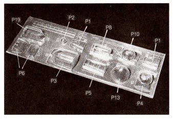
PREPARING THE PLASTIC PARTS
Photos 35 thru 37
|
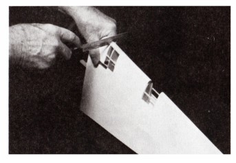
The opaque (non-transparent) plastic parts should each be lightly numbered with a soft lead pencil then cut apart with a pair of scissors (a part number is adjacent to each plastic part). Three pages of the enclosed "Balsa Model Kit" folder enclosed is devoted to the cutting, cementing and painting of Guillow vacuum formed plastics parts. If not familiar with these techniques, it will pay to read the information supplied before cutting out the parts.
Using the point of a model builders knife or a single-edged razor blade, score the plastic part as close as you can at the trim points. The score should be deep but not through. Score twice if necessary. After scoring, gently bend the excess material back and forth until it breaks away. Now
|
sand all the edges to smooth them off.
Use a plastic cement when joining the matching halves of parts that require joining before being added to model. After cement has dried, lightly sand the joints for a smooth finish.
Except for the special nacelle cut-outs to accommodate the motors of a U/Control model, the opaque plastic parts are ready to be attached to the model.
The clear plastic parts are made of acetate that is a different material than used for the opaque plastic parts. Extra special care should be taken when cementing clear plastic parts in place and when painting in the window separations since a smear of cement over a window area will mar its clarity.
|
|
Before starting paint job be sure and read the instructions for Painting the Plastic Parts printed in the Balsa Model Kit folder.
Always test cements and paints on scrap pieces of plastic before use on finished parts to determine adhesion and coverage. For the most satisfactory results on models, it is recommended that for the final paint coats, the entire model be painted with enamel. The non-plastic areas can be painted with clear dope to build up a paint base then enamel can be used overall for the finish. Always remember, enamel can be painted over dope but dope cannot be painted over enamel without spoiling the finish. The following general information should be helpful when you decide to paint your model.
There are two types of fast drying colored dopes you can use on your model. One is Nitrate and one is Butyrate. The Butyrate is fuel resistant but the Nitrate is not. You can also use a plastic base type paint finish (see your hobby dealer) that is also fuel resistant and fast drying. You can use any of these three types for non-flying scale version of the model, but you must use a fuel resistant type if you use a gas engine, because the potent materials in the fuel will soften and dissolve the nitrate dope. This, of course, will spoil your finish.
Generally, the colors on the war planes were of a dull or semi-gloss finish. Most of the dopes are a glossy paint. Ask for and use a paint that has authentic dull finish and makes for real scale effect when used. The proper colors can be had by intermixing the paint colors. Also, the glossy paints can be used and dulled after they are dry by using an abrasive mixed with water,
|
such as Bon Ami powder. Rub the surface just enough to take away the high gloss and then wash the powder off with clear water.
The painted finish of your model will only be as good as your preparation. The consistency of the paint should be such that it does not dry out while being applied and still not so thin as to run easily. Use a good 1/2" to 3/4" brush and, assuming that the model is clear doped, smooth and clean, proceed as follows: Paint all of the edges first. Paint one half of the fuselage at a time starting at the nose and proceeding to the rear.
Next, paint the top and bottom of one wing panel and stabilizer-elevator and one half of the fin-rudder. When dry, so you can handle the model, paint the remaining half of the model. On the fuselage, brush on all coats the length of the fuselage. On the wing and tail surfaces, brush each alternate coat on in opposite directions, finishing with the last coat running in the same direction as the fuselage.
Apply only enough colored paint to give complete coverage, as colored paint is heavy. Usually two or three coats is enough. When more than one color is required on a model, finish the lightest color first and the darker color last, because dark colors cover over light better than light over dark. Allow sufficient time between coats for the paint to dry.
After the model has been painted, ink in the control surface lines-refer to drawings for positions. Apply decals to model in positions shown following instructions on back of decals. Add finish details such as remaining "J" and "P" parts, guns, aerial masts, aerials and the small details shown in Section 18, Plan "G"
|
COVERING THE AILERIONS, ELEVATORS AND RUDDER WITH CARDSTOCK
PAINTING AND FINISHING THE MODEL PARTS
|
Although some of the photos listed show "uncovered" frames being assembled, all should be covered with tissue or iron-on film before assembly.
First slide the stabilizer into position in fuselage, line up carefully then cement in place. Photo 38. Next, turning to Section 22, Plan "E", cut out paper part J24 and cement it to former B1.
Assuming that the vacuum formed plastic parts for the fuselage have been cut out, trimmed to shape and "edge sanded", (except for P11), cement them to the tissue covered fuselage frame starting with the nose cone (P13) and working back to the tail cone (P9). Parts P7 are to be "fitted" to the top of stabilizer trimming them if needed for a smooth fit before being cemented in position.
To do a neat job of cementing parts to the model, follow this procedure - first, locate the part on the model without cement and, while holding it in position, use a very soft lead pencil to mark around the part and onto the model. Thus, when cementing a part to model, the part can immediately be positioned without guesswork. Plastic parts should be held in position until dry with pins or with rubber bands.
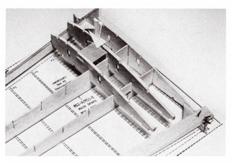
Cement the rudder to the fuselage, sighting it carefully for alignment before the cement dries using pins if needed for support. Photo 39. If not prepared previously, assemble the main landing gears as shown in Section 12, Plan "F". When complete, cement them into the prepared slots in the bottom of the wing panels. Cement plastic parts P14 and P15 to the top of the wings. Next cement the plastic half shells (P27 thru P34) to the wing and nacelle
|
frames attaching the lower halves first. (It will be necessary to make small slits in the inboard shells to accommodate the main landing gear wires.) The upper half shells have small lips that overlap the bottom shells. These can be trimmed off if a smoother joint appearance is desired. Any "gaps" appearing where the nacelle shells touch the wing surface should be filled in with plastic balsa filler or similar material. Sand smooth when dry.
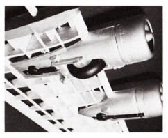
Refer to Section 15, Plan "F" for instructions for assembling and installing the four scale propeller units. Take special note that the dummy plastic engines (P24) and the propeller hub units (less propeller blades) are assembled before being cemented to nacelle formers G1 - this is shown in Sections 13 and 14 of Plan "F". Photo 40.
Cement the four plastic cowls (PI7) to the nacelles then cement the carved and sanded balsa propeller blades to the plastic hubs: Add parts P36 to the inboard nacelles then parts J13 to the top of both wings - see small three view plan on Plan "A".
Due to the wing rail structure, the wings can be permanently cemented to the fuselage or merely set in position for removal as desired. For permanent attachment, the plastic top fillets (P37) and cardstock bottom fillets (J 16) are cemented to both the wings and the fuselage. For removable wings, set the fillets in position but only cement them to the wings. When dry, the wings, with fillets in place, can be removed and replaced as desired. Photo 41. The remaining wing "J" parts such as wheel wells, simulated landing lights, etc. are only added after the model has been painted. Photos 42 and 43 are views of the assembled model.
|
ASSEMBLING THE MODEL See Drawing No. 9