


KIT 1403 F-16a Fighting Falcon
Wing Span: 12 1/8" Length: 18½" Scale: 1/30(approx.)
BUILDING INSTRUCTIONS
|
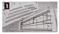
Pin Plan C to a workboard and cover with a sheet of protective film such as Saran Wrap. Start wing assemblies by pinning W1's (tips) to layouts. Next glue and pin W2's against W1's then add W3's gluing and pinning them against the W1's.
Cut the bottom spars from a piece of 1/16" sq. strip stock. Pin over layout with ends glued to W1's. PHOTO 1.
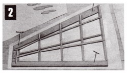
Beginning with the W4s (wing ribs), glue all ribs to the W2's, bottom
|
spars and against the W3's. Be sure to line them up with the printed lines making certain that they do not lean to one side or the other. Cut the top spars then glue them in the rib notches and to the top of W1's. PHOTO 2. Note the use of pins to hold parts in place during assembly.
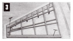
Glue sub-ribs W8, W9, W10 and W11 to the W2's and top spars. PHOTO 3. Let all glue joints dry hard before moving on to the next step.
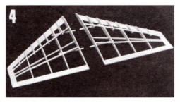
Carefully pull out pins then remove wing frames from layout. Cut the
|
|
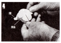
1/16" sq. alignment strips to exact length and glue them in notches in bottom of ribs. Let glue dry hard.
When dry, trim off any excess 1/16" sq. spar lengths. PHOTO 4.
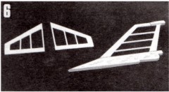
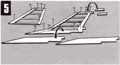
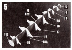
Stabilizer and rudder frames are assembled over their respective layouts much like the wing frames. The die-cut parts are glued and pinned to each other in numerical order then the 1/16" sq. cross braces
|
are cut and added. PHOTOS 5 and 6.
Let glue dry hard before removing frames from layouts.
Note how rudder parts R6 and R7 are glued to each side of rudder frame as described in PHOTO 5 copy. When glue has thoroughly dried, carve and sand parts R6 and R7 to blend into the main rudder frame.
Finally sandpaper all frames smooth for tissue covering later on.
|
|
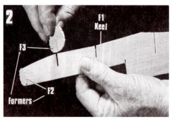
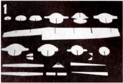
PHOTO 1 shows all of the die-cut fuselage parts laid out ready to use. before proceeding, be SURE the internal 1/16" square notches have been cut in parts F11 as shown by drawing on Plan B, Miscellaneous Parts Area. The exact location of notches are indicated by the punch marks in the F11 parts.
To start, test fit formers F3 thru F10 by slipping them into their respective
|
slots in center keel F1. PHOTO 2. If a former fails to slip easily into its keel slot, do NOT force into position. Instead, using a razor blade or knife, slightly widen any slot that binds until a smooth fit results.
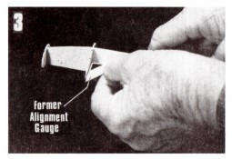
Beginning with F2 and continuing thru F7, glue formers to the center keel using the die-cut Alignment Gauge to align them at exact right angles (90°) to
|
|
attached to fuselage.
The attachment of the stringers (1/16" sq. balsa strip stock) is the next job. PHOTO 7. Study the top and side views to see where the stringers start and stop. All fit into the 1/16" sq. former notches except for two short stringers that butt against F9 from F10 - see F9 pattern on Plan B, Block 3.
It is best to attach stringers in pairs - one on one side of the center keel then the corresponding one on the opposite side. This will prevent
|
tension that might warp the frame if all stringers on one side of the center keel where to be glued in place at one time.
PHOTO 7 also shows how adhesive is applied when gluing stringers to the formers - a small drop in each corner is sufficient. Also shown is the use of common pins to wedge stringers in place if former notches are too wide. This should be done carefully to avoid splitting formers.
|
|
the keel before the glue hardens PHOTO 3. This alignment check is very important to insure that the fuselage frame finishes up straight and true.
Carefully line up formers F8 and F8A and glue them together. PHOTO 4. Set aside until dry. When dry, glue the double former and formers F9 and F10 to the center keel. PHOTO 5. Now recheck the alignment of all formers. If any
|
have twisted out of alignment, carefully cut away from the keel and re-glue in place.
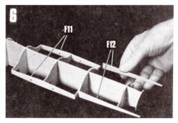
Select parts F11 and F12 and glue them to formers F6, F7, F8/F8A and F9. PHOTO 6. Be SURE parts F11 are glued to formers F6, F7 and F8 with printed word "top" up. If attached upside down, the wing will not fit properly when
|
|
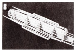
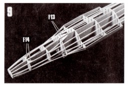
PHOTO 8 shows the stringer attachments (bottom view) from F5 back to F10. PHOTO 9 shows stringer
attachments (top view) from F8/F8A forward to F2. Next glue small parts F13 and F14 in place as shown on top and side views.
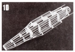
PHOTO 10 shows the completed stringer installation (bottom view).
|
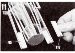
Next glue the four F15 parts to former F9 and F12 as shown in PHOTO 11.
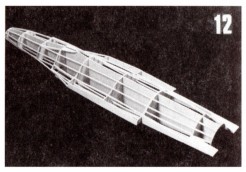
Finally, PHOTO 12 shows the completed top view of the fuselage frame with all stringers attached.
The drawings below show the installation of the air intake unit. Do not try to install until so directed on Plan C, Block 9
|
|
Important Note! Although many of the photos in the following Blocks show assembled non-covered frames, all frames that are to be tissue covered should be covered BEFORE they are assembled.
Optional: If you prefer to assemble a non-tissue covered model such as the illustration on the box cover, disregard these instructions.
If you have never covered a balsa model with tissue before, it is important that you read the instructions in the General Information Sheet under the heading "Tissue For Covering Model Frames". In addition to hints on tissue covering, valuable information is supplied on
|
the use of white glue diluted with water as a wood priming agent and as an adhesive for gluing tissue to wood.
The photos above show top and bottom views of the tissue covered fuselage as well as the tissue covered wings and tail surfaces. The wings and tail surfaces are comparatively easy to cover having mostly flat surfaces. The fuselage, consisting of both flat and curved surfaces, is more of a challenge since it requires the application of smaller segments of tissue to avoid unsightly wrinkles. A scheme for covering a typical fuselage (an F15) is provided in the General Information Sheet.
|
|
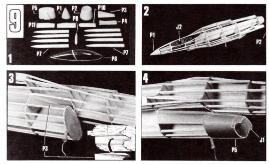
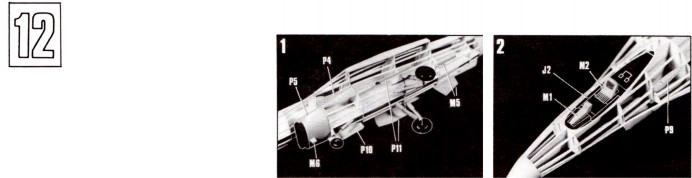
PHOTO 1 shows all of the white vacuum formed plastic parts and canopy cut to shape ready for assembly or attachment to model. (See General Information Sheet for additional information on this subject.) They should be color painted first - see color scheme on Plan D.
PHOTO 2. Cut out cockpit deck (J2 on printed cardstock sheet). Glue to top of fuselage frame. Glue nose cone P1 to former F2 and tailpipe P2 to former F10.
PHOTO 3. Carefully fit and glue airduct
|
fillets P3 and P4 to stringers and formers F5 and F6 as shown In photo and by drawings on Plan D. If there is any overhang, trim off with a sharp pointed knife blade AFTER glue has dried hard.
PHOTO 4. Prepare air intake duct P5 as shown on Plan D. Cut out and glue cardstock part J1 to one side of former F-16. Next cut and glue card-stock part J1 to front of P5. Clue former F-16 Inside the back of P5. When dry, line up and glue P5 to the front of former F5.
|
|
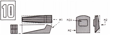
Cut out parts M1, M2 and M2A on die-cut balsa sheet D. Glue the sections together as shown above. When dry, carve to
|
shape indicated. Sand smooth then set to one side until final assembly of modeI.
|
|
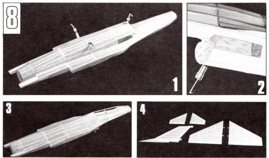
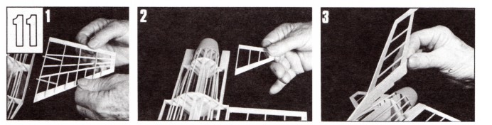
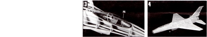
The photos in Blocks 11 and 12 show a model without tissue covering. Whether "covered" or not, the model is assembled in exactly the same way.
PHOTO 1. Glue left wing to fuselage part F11 with the 1/16" sq. spar extensions fitting into the 1/16" sq. alignment holes. Check alignment carefully.
|
Attach right wing in a similar manner.
PHOTO 2 shows the attachment of the left stabilizer following which the right stabilizer is glued in position. Sight alignments carefully!
PHOTO 3. Rudder attachment. See Plan D for position. Align carefully before glue dries hard.
|
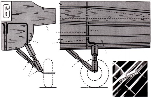
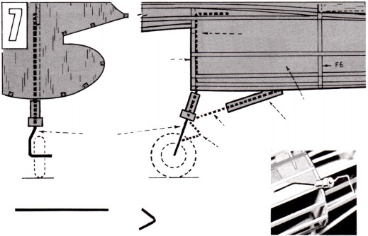
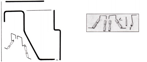
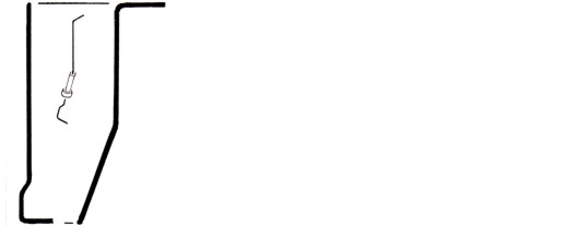
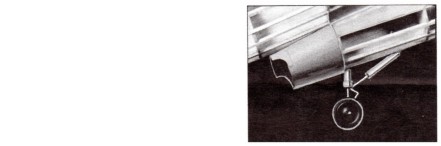
LEFT MAIN GEAR ATTACHMENT
—see block 10 also.
MAIN GEAR INSTALLATION
NOSE GEAR ATTACHMENT
—see block 10 also.
NOSE GEAR
LEFT GEAR SHOWN IN PHOTO
MAIN GEAR
INSTRUMENT DECK
BACK OF PILOT'S SEAT