

KIT 1402 F-14 Tomcat Wing
Span: 19"(extended), 10"(swept back) Length: 18½" Scale: 1/40(approx.)
BUILDING INSTRUCTIONS
|
B5A and B6.
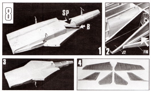
FOR TISSUE COVERED MODEL ONLY. Glue two short 1/16" sq. filler strips between the stringers and against the front of F6 - both sides of fuselage. Make two tracings of pattern SP on white bond paper (not supplied) - cut to shape. Glue the patterns to both sides of fuselage frame - see sketch below and photos in Block 8.
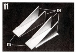
Assemble the two dummy air intake ducts as shown in PHOTO 11
|
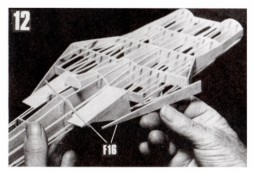
PHOTO 12. Glue the air intake ducts against both sides of fuselage and against F6. When dry, glue die-cut pieces F16 to the F13's and against the sides of the F14's. Finally cut and glue in place the 1/16" sq. strips that fit against the F14's and between the F16's and former F6.
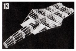
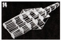
PHOTO 13. Top view of completed fuselage. PHOTO 14. Bottom view.
|
|
This kit is supplied with die-cut balsa parts to build both "fixed" and "swept" wing frames (the latter shown on Plan E, Block 13). Either set may be permanently attached to the fuselage or, by the use of small common pins or light tack gluing, the sets may be interchanged at will.
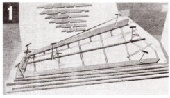
Pin Plan C to, a workboard and cover with a sheet of protective film such as Saran Wrap. Start wing assemblies by pinning W1's (tips) to layouts. Next glue and pin W2's against W1's then add W3's gluing
|
and pinning them
against the W1's.
Cut the bottom spars from a piece of 1/16" sq. strip stock. Pin over layout with ends glued to W1's. PHOTO 1.
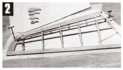
Beginning with the W4 s (wing ribs), glue all ribs to the W2's, bottom spars and against the W3's. Be sure to line them up with the printed lines making certain that they do not lean to one side or the other. Cut the top spars then glue them in the rib notches and to the top of W1's. PHOTO 2. Note the
|
|
use of pins to hold parts in place during assembly.
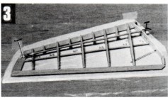
Glue sub-ribs W10, W11, W12 and Wl3 to the W2's and top spars. PHOTO 3. Let all glue joints dry hard before moving on to the next step.
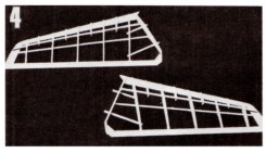
Carefully pull out pins then remove wing frames from layouts. Cut the 1/16" sq. alignment strips to exact length and glue them in notches in bottom of ribs. Let glue dry hard. Add small filler blocks at ribs W4 and W2.
When dry, trim off any excess 1/16" sq. spar lengths. PHOTO 4.
|
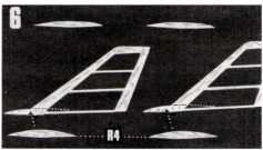
Stabilizer and rudder frames are assembled over their respective layouts much like the wing frames. PHOTOS 5 and 6.
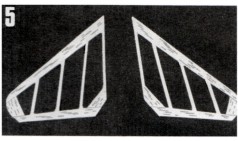
Rudders only - glue two of the die-cut R4 pieces on each side of each rudder. When dry, carve or sand R4's to the streamlined, tapered shape shown by drawings.
Lightly sandpaper all frames smooth for tissue covering.
|
|
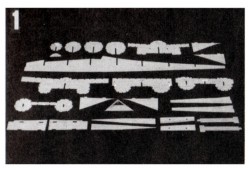
Before starting, be SURE that the internal 1/16" sq. notches have been cut in formers F6 and F8 - see Block 3 on Plan B. PHOTO 1 shows all the die-cut fuselage parts laid out ready for use.
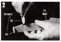
To start, test fit all formers (F3 thru F9) by slipping them into their respective slots in center keel F1. PHOTO 2.
If a former fails to slip easily into its keel slot, do NOT force into position.
|
Instead, using a razor blade or knife, slightly widen any slot that binds until a smooth fit results.
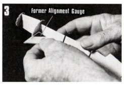
Beginning with F2 and continuing thru F8, glue formers to the center keel using the die-cut Alignment Gauge to align the formers at exact right angles (90°) to the keel before the glue hardens. PHOTO 3.
|
|
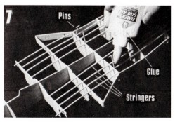
The addition of the 1/16" sq. stringers is the next job. The stringers are glued in the former notches except for the few that butt against formers - see Former Patterns in Block 3. Study the plans to see where stringers start, stop and in some cases butt together in the center of a former notch.
Starting with the top rear section of the fuselage frame, cut and attach
|
the
stringers that run between formers F6 and F11. PHOTO 7.
It Is best to attach stringers in pairs - one on one side of the center keel then the corresponding one on the opposite side. This will prevent tension that might warp the frame if all stringers on one side of the center keel were to be
glued in place at one time.
|
|
This alignment check is very important to insure that the fuselage frame finishes up straight and t rue.
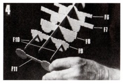
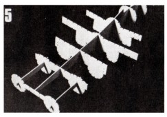
Next slip the two die-cut alignment sticks F10 into notches in former F9 (Photo 4) - lightly glue in place. Glue F9 to center keel F1 then glue F11 to the end of F1 and F10 alignment sticks. Cement entire structure together
|
lining up
carefully before the glue dries hard. PHOTO 5.
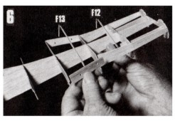
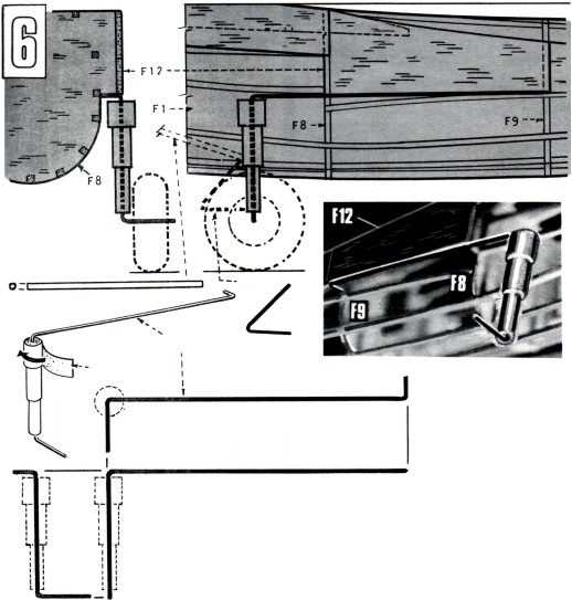
Select the two die-cut F12 pieces then fit and glue them to formers F8 and F9. When dry, lightly score the F12' s at former F9 with the point of a razor blade then bend the rear portions back until they rest against former F11 -
glue in place. When dry, add parts F13. Photo 6.
|
|
PHOTO 7 shows how adhesive is applied when gluing stringers to the formers - a small drop in each corner is sufficient. Also shown is the use of common pins to wedge stringers in place if former notches are too wide. This should be done carefully to avoid splitting formers.
|
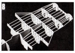
PHOTO 8 shows the 1/16" sq. top stringers glued in place.
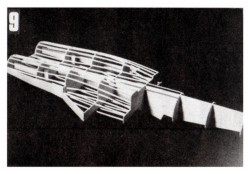
Now attach the stringers on the bottom of fuselage between formers F6 and F11. PHOTO 9.
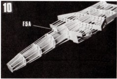
Add the top and bottom stringers that run from F2 to F6. Glue small former B5A in place on the two top center stringers. Photo 10. Add short stringers
|
|
Important Note! Although many of the photos in the following Blocks show assembled non-covered frames, all frames that are to be tissue covered should be covered BEFORE they are assembled.
Optional: If you prefer to assemble a non-tissue covered model such as the illustration on the box cover, disregard these instructions.
If you have never covered a balsa model with tissue before, it is important that you read the instructions in the General Information Sheet under the heading "Tissue For Covering Model Frames". In addition to hints on tissue covering, valuable information is supplied on
|
the use of white glue diluted with water as a wood priming agent and as an adhesive for gluing tissue to wood.
The photos above show top and bottom views of the tissue covered fuselage as well as the tissue covered wings and tail surfaces. The wings and tail surfaces are comparitive1y easy to cover having mostly flat surfaces. The fuselage, consisting of both flat and curved surfaces, is more of a challenge since it requires the application of smaller segments of tissue to avoid unsightly wrinkles. A scheme for covering a typical fuselage (an F15) is provided in the General Information Sheet.
|
|
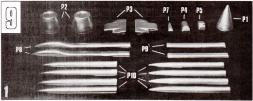
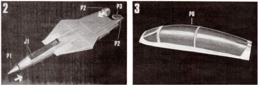
PHOTO 1 shows all of the white vacuum formed plastic parts cut to shape ready for assembly or attachment to model. (See General Information Sheet under Plastic Parts for information on this subject.) They should be color painted before attachment to model - see color scheme on Plan A.
PHOTO 2. Cut out cockpit deck (J1 on printed cardstock), fold as indicated, then glue to top of fuselage. Glue nose cone P1 to former
|
F2 and tail cones P2 to former F11. Using plastic cement (sparingly), cement the P3 halves together and fit on former F11 between the P2's. Trim where necessary for a good fit then glue in position.
PHOTO 3. It is easier to paint the canopy separations before cutting it from its base. This will provide an easy to see cutting line. Canopy shown painted and separated from base.
|
|
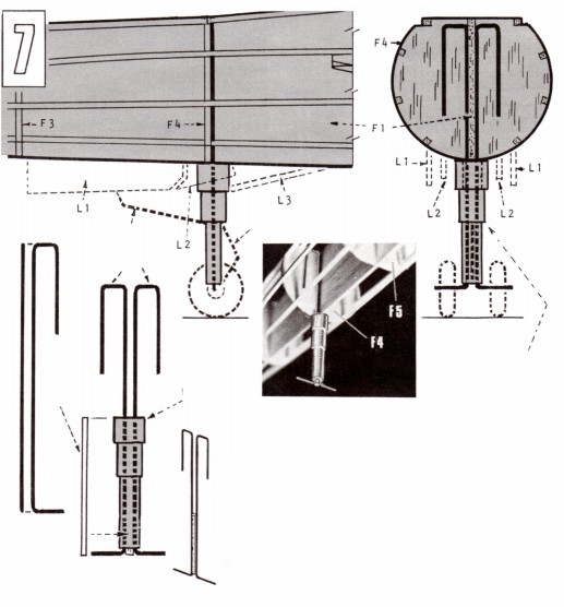
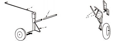
the two small wheels on the nose gear axles. Place a drop of glue on the axle ends to prevent the wheels from dropping off.
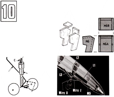
Turning to block 6, cut the two strut supports from the
|
1/16" diameter dowel stock supplied. Cut and bend to shape the two "B" wires. Glue strut supports and wires to main gear struts. Add wheels and apply a drop of glue on the end of each wheel
axle.
|
|
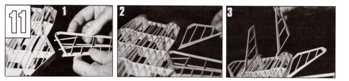
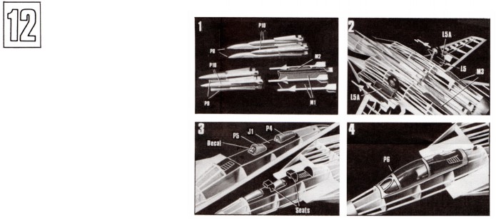
Note that the photos in Blocks 11 and 12 show the model without tissue covering. Whether "covered" or not, the main elements of the model are glued together in the same way.
Photo 1 shows the left wing being glued to fuselage part F13 with the short 1/16" sq. strip extensions ready to fit into the 1/16" sq. alignment holes. Check alignment before glue dries. Attach
|
right wing in a similar manner.
Photo 2 shows the left stabilizer being attached after which the right stabilizer is added. Sight alignment from front and back before q1ue sets up.
Photo 3 shows the rudder attachments. See side, top and rear views on Plan D for exact positioning of these two units.
|
ASSEMBLED NOSE GEAR
NOSE GEAR PATTERN
NOSE GEAR ATTACHMENT
DETAIL OF NOSE GEAR
ASSEMBLY
DETAIL OF MAIN GEAR ASSEMBLY
EXPLODED VIEW OF MAIN LANDING GEAR DOORS