

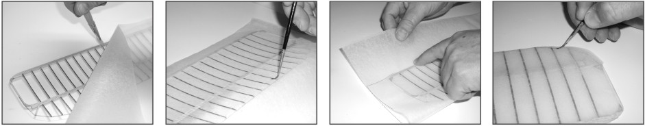

The wings should be done and ready to tissue. The wings are a very large visual part of this 1903 Wright Flyer so take your time and do a good job !! Tissuing is done by gluing tissue to the balsa wing frame and shrinking the tissue with a mist of water to tighten the tissue. The glue mixture to adhere the tissue to the frame is a 50% white glue and 50% water mix. To mist the tissue use a spray bottle with water in it. Mist tissue from a distance of about two feet to let the tissue become gently wet. Start the tissuing by cutting a piece of tissue a couple inches wider than the wing and about 10” high, this will be enough to cover one whole wing, top and bottom. It’s easiest to do the underside of the wing first so lay the wing upside down on your work surface and paint some 50/50 glue mixture along the leading edge and wing tips, then lay your tissue over the wing as shown in the 1st picture. Now roll your tissue sheet down onto the underside of the wing and paint some glue mixture thru the tissue onto the wing ribs and spar, see 2nd picture. Once this bottom side is dry, trim the excess tissue off the leading edge and wing tips. Now fold your tissue around the trailing edge of the wing and up over the top surface, see 3rd picture. Paint some glue mixture onto the leading edge and wing tips, pull the tissue gently and evenly over the wing. To close the tissue around the wing tips apply a liberal amount of glue mixture to the tissue outside the thread, see 4th picture. Pinch the tissue together so that the top and bottom tissue become joined on the outside of the thread. When the wing is all tissued and dried the excess should be trimmed off. You can then mist the wing structure with some water, this will help stretch and tighten up the tissue removing any small wrinkles or sags. It is recommended that the wing be held / pinned down flat when misting with water to help minimize any warping as the water dries and the tissue shrinks taut.
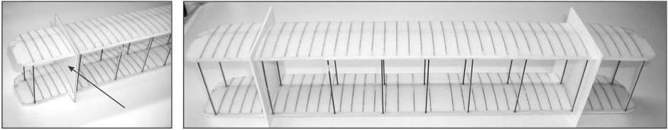
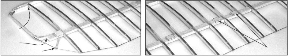
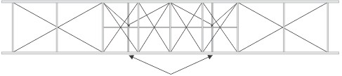
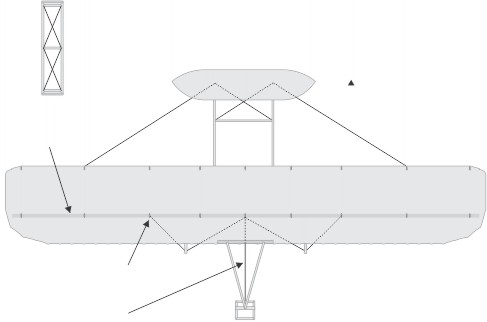
Now you’ll need to construct the wing ends (U shaped pieces) out of 1/16” sq. stock and laser cut fillets, build and glue them over the plan layout, do not glue to wing at this time. Lift off plan and glue to the wing at the bottom of the leading edge and to the middle of the wing spar. See picture on left above. Make small filler wing rib out of 1/16” x 3/32” stock. On the BOTTOM wing, you will have to add some support blocks for the wing struts and motor mounts. These are made from scrap pieces of 1/16” thick balsa, see picture above right. After that is a good time to sand your wing frames lightly to get them smooth and ready for tissue covering. See the Side View of Wing Ribs for shape. The trailing edge of these wings are made of thin thread, cut a piece a bit longer than the wing off the spool provided in the kit. This thread starts on the wing end and is glued to each wing rib tip along the back of the wing until it reaches the other wing tip. This is the most tedious of the wing construction steps, make sure the thread is taut between each rib. It may be helpful to make a small groove in the tip of the ribs to hold the thread in place, but if you do the groove should not be deeper than the thickness of the thread.
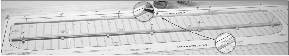
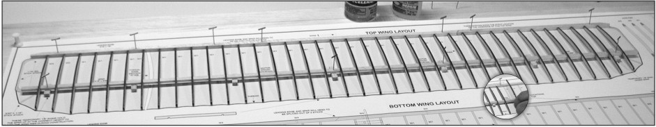
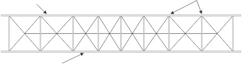
Once the Leading Edge and Wing Spar are pinned down over the plan, you are ready to start putting in the wing ribs. Please note that the 4 wing ribs (W2 and W3) on both wing tips are shorter, the rest of the wing uses the W1 wing rib. Place a rib over the wing spar and against the leading edge, make sure it is straight and glue into position. Repeat this process until all the wing ribs are glued in place. Once the glue is dry your wing is now ready to lift up from the building plan.
KIT 1202 - 1903 WRIGHT FLYER - BUILDING INSTRUCTIONS
1. Building the Wing Frames
Before starting construction of your model, study the plan and these building instructions carefully so that you have a complete understanding of the step-by-step method of building this 1903 Wright Flyer display model. Guillow engineering has provided you with the most up to date method for building this 1903 Wright Flyer model. Only careful attention to detail will insure the success of your efforts. Most prize wining models are the result of patience and careful workmanship. You too can achieve success by following the example of champion model builders by working slowly and carefully at all times. In this model are laser cut parts that are held in the balsa sheet by small "notches". To remove parts from the balsa sheets carefully cut the notches with the tip of your modelers knife, this allows the parts to become loose of the balsa sheet. Some tools that you will need to build this model are a building board, pins, glue, modelers knife, plastic wrap, fine sandpaper, white glue and a small paint brush.
3. Building the Fuselage Frame
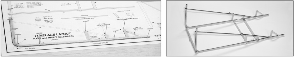
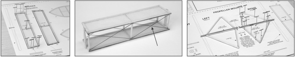
Build the fuselage over the shaded parts of the FUSELAGE LAYOUT as you did the wing. Pin in place and glue parts F1, F2, F3 and strip stock as shown in picture above. When glue is dry, remove this fuselage side from plan and repeat process for second side of fuselage. Glue a F4 to the inside of each fuselage side. Glue the angled piece of 1/16"sq. strip stock to F2, F4 and the 1/16" x 1/8". Pin the two rear fuselage braces to the plan and glue the two sides of the fuselage over them making sure the F4's are on the inside and the frames are 90 degrees to the building surface. Remove from plan and glue the forward fuselage brace and rail guide to fuselage.
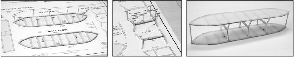
Build the elevators over the shaded parts of the UPPER and LOWER ELEVATOR LAYOUT. When dry lightly sand all sides of the frames. Cover the frames with tissue, using the 50/50 glue mixture, this is done with one piece of tissue for each side of the elevator. When dry cut out the tissue in the center of both E5's. Glue the 1/16" sq. strip to the bottom of each elevator. Now build the elevator struts over the shaded plan layouts. When dry assemble the elevator as shown in the 3rd picture above, making sure the struts are facing the correct direction and are 90 degrees to the elevator.
4. Building the Rudder and Propeller Mounts
Build the rudders over the shaded parts of the RUDDER LAYOUT as shown above. Cut four pieces of tissue slightly larger than the perimeter of the rudder and cover the frames with tissue (one piece of tissue for each side of the rudder). When the tissue is dry add the six 1/16" sq. rudder struts joining the two rudders together, as shown in the 2nd picture. When gluing together make sure they are lined up to each other. Glue the rudder braces to the top and bottom of the rudder assembly. Now would be a good time to add the rigging wires. Build the propeller mounts over the shaded parts of the plan as shown above. Cut and add wire for propeller shaft.
To align the wings first cut out the wing jigs on the bottom of the box. Slide the wings into their slots in the jigs, make sure the to put the top and bottom wing into their respective slots. Note: the front and back struts are different shapes and some struts have center holes so take some time and layout the wing struts correctly. Make sure the wings are directly over each other. Glue struts in place using a small amount of glue on the tips of each strut. Note: the holes in the struts are for rigging lines, when gluing be careful not to fill in. When glue is dry your wing will be rigid enough to cut the wing jigs off.
Find a suitable work surface (if not our balsa workboard then something else flat that will accept pins, such as a stiff piece of cardboard or ceiling tile) and pin your wing plan down. You should then cover your plan with a thin piece of plastic wrap so your glue doesn’t stick and ruin the plan during building. Now you are ready to build your Wright Flyer wings. Both top and bottom wings are constructed VERY similarly, with the exception of some wing rib locations and some strut support blocks - described below. Start by pinning the 1/8" x 3/16" Leading Edge over the plan, you will have to splice and glue the sticks together as shown to have one continuous Leading Edge. The top corners of the Leading Edge are angled, now is a good time to cut the angle on the ends with you hobby knife. Next join the two 3/32” x 3/16" balsa sticks which make up the Wing Spar, join in a simular manner as the leading edge. Next put some 1/8” spacers, cut from 1/8" x 3/16" stock, down and then pin your Wing Spar over the plan as shown.
Glue to
center of
wing spar
Glue to
bottom of
leading edge
Copyright 2003 by Paul K. Guillow, Inc., Wakefield, MA USA
Glue rudder support W8 to top wing.
Glue top rudder strut to rudder support.
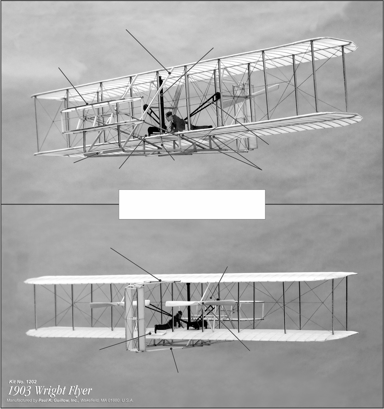
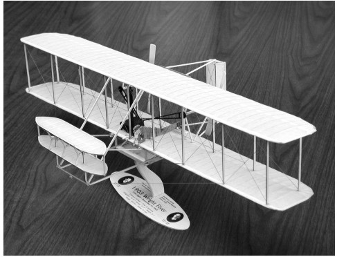
1903 WRIGHT FLYER ON STAND
Add propeller mount
rigging wires
Install the two propeller mounts making sure the wire is facing
towards middle of model. Put chain drives on back of propeller mounts.
Using a common pin attach the two chain dive ends and fly wheel to engine,
making sure the engine sits on ribs. Glue in place
Install the two propellers onto the motor mount shafts.
Secure by fashioning two balsa washers glued to the end of the shafts
Glue completed pilot footrest
and pilot yoke in proper position on bottom wing.
Glue assembled pilot to yoke and footrest.
Glue bottom rudder strut to fuselage.
Glue completed rudder between top and bottom rudder struts.
We do not show ALL rigging and control wires
that were on the original 1903 Wright Flyer.
To add more detail consult your local library or internet.
Slide fuselage pulley shaft through the holes in F4.
Make sure pulley wheel and handle are on shaft before it is all the way inserted.
Glue the shaft in place. Glue handle in upward position by pilots hand.
Add thread from fuselage pulley wheel around elevator pulley wheel and glue in place.
Glue completed radiator against
middle strut and bottom wing
Slide the completed elevator down onto F1's.
Make sure the F4's are on the inside of the elevator struts.
Slide pulley shaft through the aligned holes in F1 and E6.
Make sure pulley wheel is on shaft before it is all the way inserted.
Glue the shaft in place.
Make and glue in place the two 1/16" x 1/8” fuselage supports.
Glue 1/16" sq. cross member between fuselage supports, just above F4's.
Make and glue in place
the 1/16" x 1/8' center wing support
Center wing over fuselage.
Attach completed wing to fuselage making sure the
strip stock is glued to the leading edge and wing spar.
Once the components are installed on the wing, rigging can be started.
Insert the thread through the holes in the top and bottom of the struts
as shown, then glue ends and trim off excess.
Add the horizontal rigging.
All tissuing should be done before final assembly. The wing and rudder rigging should be done before attaching to the fuselage. It is easier to paint the components of the Flyer before assembling the model. If you would like to display your model on a stand we have provided a die cut balsa sheet with the stand parts on it that you can assemble.
Color Scheme
Black: Propeller Mounts, Engine, Gears, Radiator
Medium Brown: Propellers
Copyright 2003 Paul K. Guillow, Inc.
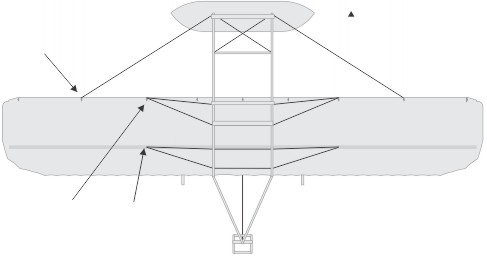
RIGGING WIRE ATTACHES
FROM THE CENTER OF BOTTOM
RUDDER BRACE SUPPORT
TO TOP OF CENTER STRUT
NOTE: RIGGING IS ON FRONT
AND REAR OF RUDDER