600 Series Piper Super Cub 95

Ask other modelers for a little help / knowledge ?

600 Series Piper Super Cub 95

Postby Phugoid » Mon Aug 09, 2010 5:10 pm

Was looking for something simple to and quick to build as my daughter has been bugging me to build her another model and saw one of these kits cheap on ebay - less than £10.

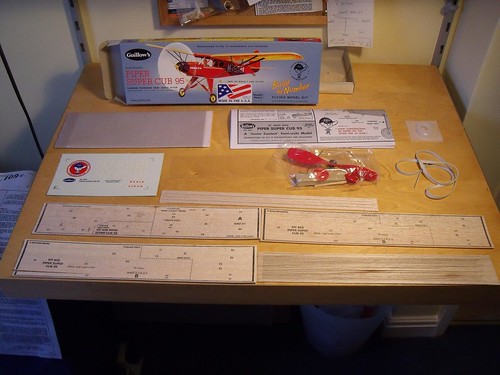
The kit is good value the balsa sheets are the lightest ever in a guillows kit (7.5lb) and it even has a reasobale sized prop!

The kit rubber is a bit on the rough side however it could probably make it fly. The only thing wrong with the kit is that 3 out of the four pieces of 1/4" strip actaully measure 3/16"! It is a pity really as the wood is ideal (nice and hard) for leading edges. I'll simply cut new strips for these from stock, but it would be a pity if someone bough this for their first kit and was let down by such a silly error

Image
Phugoid
 
Posts: 952
Joined: Wed Jan 20, 2010 8:17 am

Postby Phugoid » Mon Aug 09, 2010 5:49 pm

I think I will try and emulate the box artwork and abandon the rather dull grey tissue supplied. The red fuselage and yellow wings should make quite an attractive little model.
Phugoid
 
Posts: 952
Joined: Wed Jan 20, 2010 8:17 am

Postby kittyfritters » Wed Aug 11, 2010 7:00 pm

It doesn't look bad that way.

Image

This model has been refitted with a Gizmo Geezer PFW-70 prop and hub assembly and flies successfully indoors and outdoors.

(Photo was taken on a table that had been set for a 4th of July party.)
kittyfritters
 
Posts: 697
Joined: Tue Jan 03, 2006 6:58 pm
Location: California

Postby Phugoid » Thu Aug 12, 2010 6:59 am

Looks good, Have made zero progress on mine yet been doing a bit of canopy "plunge moulding" for a glider - It's good fun!

The pics are very useful as a reference......... did you post a build thread?

Andrew
Phugoid
 
Posts: 952
Joined: Wed Jan 20, 2010 8:17 am

Postby kittyfritters » Thu Aug 12, 2010 10:40 am

Phugoid wrote:Looks good, Have made zero progress on mine yet been doing a bit of canopy "plunge moulding" for a glider - It's good fun!

The pics are very useful as a reference......... did you post a build thread?

Andrew


I posted a short one at Virtual Aerodrome. It starts here http://virtualaerodrome.com/image_detail.html?p_aircraft_id=64&p_image_id=12444&offset=36
kittyfritters
 
Posts: 697
Joined: Tue Jan 03, 2006 6:58 pm
Location: California

Postby Phugoid » Thu Aug 19, 2010 4:37 am

The parts were reasonably well die cut and came out of the sheets neatly with about an hour’s work. I tend to bag these up by type (Formers, ribs etc) to stop them getting lost or damaged.

Contrary to the plans I’ve started with the fuselage sides, some of the bits are quite delicate until assembled so I thought it best to get them out of the way.

Since the strips are thicker than the sheet side pieces I won’t fit strip 17 over 7 and 9 until I’ve sanded the strip pieces flush with the sheet items........

Image
Phugoid
 
Posts: 952
Joined: Wed Jan 20, 2010 8:17 am

Postby Phugoid » Thu Aug 19, 2010 4:39 am

Try again....

Image
Phugoid
 
Posts: 952
Joined: Wed Jan 20, 2010 8:17 am

Postby Phugoid » Fri Aug 20, 2010 10:44 am

I've now completed both sides, removed the pins and sanded the strips flush.

Image
Phugoid
 
Posts: 952
Joined: Wed Jan 20, 2010 8:17 am

Postby Phugoid » Fri Aug 20, 2010 10:48 am

Here is former B5 being fitted, note the sqaure is tited over so it touches the frames at the same relative position and helps make sure thyat everything is nice and true.

Image
Phugoid
 
Posts: 952
Joined: Wed Jan 20, 2010 8:17 am

Postby Phugoid » Fri Aug 20, 2010 11:08 am

The plan calls for the undercart to be simply pinned in between 2 off formers B3 and glued (I assume with wood glue). but I don't think that this would be terribly strong.

I have done this firstly by "tacking" the wire into position with superglue (CA)

Image

Then I've added some scrap balsa, which is the same thickness as the wire in the positions shown. At the bottom this extra material filler may be useful later on to provide a surface for attaching tissue.

Image

I will then add the second former B3 with some epoxy on the wire (when I've got some as I've run out!) and wood glue on the balsa.
Phugoid
 
Posts: 952
Joined: Wed Jan 20, 2010 8:17 am

Postby John G Jedinak » Fri Aug 20, 2010 11:38 am

CA will hold the wire to the balsa...Luck....JGJ
John G Jedinak
 
Posts: 119
Joined: Sun Nov 15, 2009 2:53 pm
Location: Ft. Wayne In.

Postby Phugoid » Fri Aug 20, 2010 2:27 pm

Yeah probabaly, I sort of like to use the epoxy because it gap fills better, I really don't like CA in fact I hate the stuff as it tends to be brittle, hard to sand, gives you no time to adjust and you will at some time glue some part of your aeroplane to some part of your body!

However is does have its uses, like "tacking" especially the ends of a piece cotton thread to start it off when some plans call for tail skids and undercarts to be "bound with thread"

Been quiet at home so more progress today:

I'll leave this to set as is, then remove most of the pins to fit the smaller strips inside. This makes sure that nothing bets knocked or disturbed that forms the major part of the outline of the structure and makes it easier to cut the strips to size as the pins don't get in the way.

Image
Phugoid
 
Posts: 952
Joined: Wed Jan 20, 2010 8:17 am

Postby Phugoid » Mon Aug 23, 2010 2:18 am

The kit partsare obviously printed with their part ID's. Normally I would send these off on tissue covered surfaces to avoid them showing through. However the parts are already thin and I don't want to risk making them any thinner just to remove the letters and numbers.

I have found the easiest way to get rid of these is to rub them off using a little cellulose thinners on a piece of bathroom tissue.

Now you see it:
Image
now you dont:
Image
Phugoid
 
Posts: 952
Joined: Wed Jan 20, 2010 8:17 am

Postby Phugoid » Mon Aug 23, 2010 3:02 am

The pieces that form the nose are very thin in comparison the the slots in the formers, so I cut new ones from 16th scrap balsa. Nnother way I could have done this is to laminate each part to a piece of scrap to double up the thickness

Image
Phugoid
 
Posts: 952
Joined: Wed Jan 20, 2010 8:17 am

Postby Phugoid » Mon Aug 23, 2010 3:10 am

The plans calls for you to bend a bit of 1/8" strip around the cross members and the forners at the bottom. I don't thing this is wise especially given the stiffness of the wood in the kit. Fot a start off it is never good to try and bend a section around its strongest axis as it tends to be unstable and also I think it would also bend and distort the 1/16" cross member. An easier way to do this is to laminate two 1/16" strips, the first I tapered to fit inside the end of the fusalge and pinned where shown.
Image

The second piece was glued and clamped:

Image
Phugoid
 
Posts: 952
Joined: Wed Jan 20, 2010 8:17 am

Next

Return to General Building Questions

Who is online

Users browsing this forum: No registered users and 58 guests